

A rotating camera system can look perfect while stationary and still fail as soon as the axis begins to move. Video may flicker, an IP camera may drop packets, a PoE camera may reboot, or errors may appear only when the pan motor, heater or infrared illuminator is active. Those symptoms do not automatically prove that the slip ring is defective. They show that the complete rotating link needs to be tested as a system.
This guide focuses on that validation task. It does not explain which slip-ring type to choose for a PTZ camera, drone gimbal or inspection head; ByTune already covers that in the camera slip ring selection guide. It also does not replace a general Ethernet slip-ring specification. The job here is narrower: separate SDI, Ethernet, PoE, power and EMI failure mechanisms and prove that the camera link remains stable while rotating.

Map the Camera Link Before You Test It
Start with the complete path rather than the slip ring alone. Mark which equipment is stationary, which equipment rotates, and where power, video and control cross the rotary interface. The same camera can be integrated in very different ways.
| Camera Architecture | What Crosses the Slip Ring | What Can Fail During Rotation |
|---|---|---|
| Analog / coax video camera | Camera power, video coax, control | Video noise, impedance discontinuity, shield/ground problems, contact variation |
| SDI camera | Camera power plus 75-ohm serial-digital video path | Return-loss/insertion-loss margin, connector transition, shield continuity, rotation-dependent disturbance |
| IP camera with separate DC power | Ethernet pairs plus separate power circuits | Pair imbalance, crosstalk, link errors, power-to-data coupling |
| PoE IP camera | Ethernet data and camera power over the same twisted-pair channel | Network errors, voltage drop, heating, power negotiation or camera resets under load |
| Rotating network switch with multiple cameras | One uplink plus switch power | Common uplink failure, common power instability, EMI from motors or other rotating loads |
This map matters because a camera image can fail even when the video channel is healthy. A PoE camera that reboots because its supply collapses can look like a network problem. A network link that drops only when a motor drive switches may be an EMI or grounding problem rather than contact wear.
Define the Video Transport Before You Define the Test
"Camera signal" is not a technical interface. The validation method depends on what the camera actually transmits.
Coaxial and SDI Video
SDI is a high-frequency serial interface carried over a controlled-impedance coaxial path. Modern SMPTE SDI standards specify the transmission interface, including characteristic impedance and frequency-domain requirements. For example, SMPTE ST 2082-1 specifies 75-ohm coaxial interfaces for 12G-SDI and defines return-loss requirements across the relevant frequency range.
A rotary path therefore has to be treated as part of the transmission line. The complete SDI channel includes the stationary cable, connector, rotary interface, rotating cable and the receiver. A continuity test can confirm that the conductor is not open, but it cannot prove acceptable impedance continuity, insertion loss or return loss.
For troubleshooting, record whether the failure is:
- complete loss of video;
- intermittent unlock or resynchronization;
- pixel errors, sparkles or visible artifacts;
- angle-dependent dropout;
- speed-dependent dropout; or
- a failure that appears only when adjacent power circuits are active.
The symptom pattern tells you what variable to isolate next.
Ethernet / IP Camera
Ethernet over a slip ring must be treated as a complete differential channel. Pair geometry, impedance, insertion loss, return loss, crosstalk, cable/connector quality, grounding and the surrounding electromagnetic environment all matter. ByTune's Ethernet slip ring selection guide covers those design inputs in detail.
For validation, do not stop at "the link LED is on." Measure behavior while the camera is actually streaming. Useful indicators include link-state changes, packet errors, retransmissions, dropped video frames, sustained throughput and application-level interruptions.
PoE Camera
PoE adds another variable because power and data share the Ethernet cabling. IEEE 802.3 PoE families define how compatible power-sourcing and powered devices exchange power over Ethernet cabling, and IP cameras are a common PoE application. An accessible overview is provided in the IEEE Ethernet protocols reference.
The important test principle is simple: validate data and power at the same time. A PoE camera that streams correctly at low load but resets when IR illumination, heater or pan/tilt functions activate may be limited by the power path rather than by the Ethernet data path.
Use Failure Signatures to Choose the Next Test
| Observed Symptom | First Question | Most Useful Next Test |
|---|---|---|
| Video is clean while stopped but unstable while rotating | Does the failure follow shaft angle, speed or motion? | Stationary vs rotating capture; correlate errors with angle and speed |
| SDI unlocks at specific shaft positions | Is the disturbance repeatable at the same angle? | Repeat slow rotation; inspect rotary-channel transition, connectors and cable movement |
| Ethernet link stays up but frames are dropped | Are network errors rising without a full disconnect? | Monitor packet/error counters and video stream while rotating under normal traffic |
| PoE camera reboots when IR or heater turns on | Is camera input voltage falling under peak load? | Measure rotating-side supply during the event while monitoring network state |
| Errors begin when pan/tilt motor accelerates | Does the fault follow motor activity rather than rotation itself? | Compare motor/drive on vs off while keeping the camera link test unchanged |
| Several cameras fail together on a rotating network switch | Is the common uplink or switch power failing? | Test uplink traffic and rotating switch supply before testing each camera separately |
| Failure begins after cable or connector replacement | What changed in the complete channel? | Compare cable type, connector, shield termination, pinout and routing with the known-good baseline |
This symptom-first method prevents the common mistake of replacing the slip ring before the failure mechanism has been identified.
Separate Rotation From Electrical Aggressors
A camera head often contains more than the imager. Pan and tilt motors, encoders, heaters, fans, IR illuminators, wipers and motor drives can all operate close to the video or Ethernet path. If the problem appears only while those loads are switching, the key variable may be EMI, shared return current or supply disturbance.
Run the same camera test through a controlled state matrix:
| State | Rotation | Motor / High-Current Load | Camera Traffic / Video | Purpose |
|---|---|---|---|---|
| A | Stopped | Off | Active | Establish the electronics and cabling baseline |
| B | Rotating | Off where safely possible | Active | Isolate motion/contact-related effects |
| C | Stopped | On | Active | Identify EMI or power-coupling problems independent of rotation |
| D | Rotating | On | Active | Validate the real combined operating state |
If errors appear in B but not A, motion matters. If they appear in C as well, the rotating contact is not the only variable. If only D fails, the system may be sensitive to the combination of rotation, power loading and EMI.
For a broader method of separating contact noise, EMI, crosstalk and grounding problems, see ByTune's electrical noise diagnosis guide.
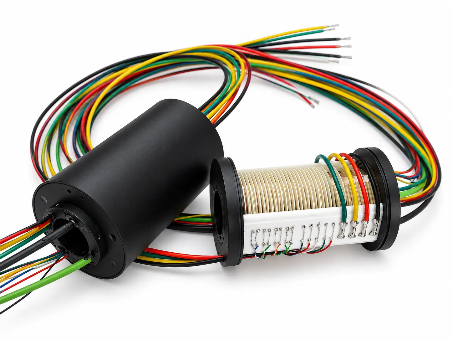
SDI Validation: Test the Channel, Not Only the Picture
A visual image check is useful, but it is not the whole acceptance test for a demanding SDI link. The rotary interface should be included in the complete channel characterization using methods appropriate to the SDI rate and equipment.
Depending on the application and available test equipment, evaluate:
- correct 75-ohm transmission path and connector/cable type;
- return loss and insertion loss across the relevant bandwidth;
- receiver lock through the full rotation range;
- error-free or acceptable error performance during rotation;
- performance at minimum, nominal and maximum required speed;
- behavior during acceleration and reversal;
- operation with adjacent power circuits active; and
- performance after the assembly reaches its normal operating temperature.
Do not copy an SDI performance limit from a different data rate. The required bandwidth and return-loss window depend on the actual SMPTE interface being used.
Ethernet Validation: Build the Complete Rotating Channel
For an IP camera, the test path should resemble the installed system:
switch / recorder → stationary cable → slip ring → rotating cable → camera
Then operate the system across the intended motion range. ByTune's industrial Ethernet validation guide recommends evaluating the entire rotating channel rather than only checking continuity through the slip ring.
Useful test outputs include:
- link-up / link-down events;
- packet-error counters;
- retransmissions;
- sustained traffic or throughput;
- video-frame or application-level interruptions;
- errors correlated with rotational position;
- errors correlated with motor-drive activity; and
- physical-layer channel measurements when project criticality requires them.
A stationary ping test is a useful starting point, not a final acceptance test.
PoE Validation: Add Power Margin to the Network Test
PoE cameras create a combined electrical problem: the same cable system must maintain Ethernet signaling while delivering operating power to the camera. The validation matrix should therefore include both network performance and rotating-side power behavior.
| PoE Test Condition | Monitor | What a Failure May Indicate |
|---|---|---|
| Camera idle / low feature load | Input voltage, link state, video stream | Baseline power and network behavior |
| IR illuminator or auxiliary load active | Camera voltage, resets, packet/video errors | Power-path drop or heating under higher load |
| Pan/tilt motor active | Network errors plus camera supply | EMI, shared-return or power disturbance |
| Continuous rotation | Voltage trend, temperature, link stability | Rotation-dependent contact or thermal behavior |
| Warm stabilized condition | Same measurements after temperature settles | Resistance/thermal margin that a short cold test can miss |
Do not assume a camera reboot is an Ethernet failure merely because the network stream disappears. Confirm whether the powered device remained energized during the event.
Grounding and Shielding Must Be Tested as Installed
Camera systems are especially sensitive to incomplete assumptions about shielding because the stationary and rotating structures may have different chassis references, motor currents may share nearby paths, and the slip ring may sit between two cable constructions.
Document:
- where cable shields terminate on the stationary side;
- where they terminate on the rotating side;
- whether the slip-ring design provides a defined shield path;
- camera chassis and gimbal/robot chassis bonding;
- signal-reference and power-return paths;
- connector shell bonding;
- proximity to motor, brake, heater or switching-power conductors; and
- any shield or ground change introduced during assembly or maintenance.
Do not disconnect protective grounds as an ad-hoc troubleshooting method. Make controlled changes that preserve electrical safety and document the return-current path.
Camera Dynamic Acceptance Matrix
A useful acceptance test combines the signal transport, mechanical motion and electrical aggressors that exist in the real camera system.
| Variable | States to Define | Acceptance Output |
|---|---|---|
| Rotation | Stopped, low speed, nominal speed, maximum required speed | Video/link stability and error trend |
| Direction | CW, CCW, reversal if used | Angle- or reversal-dependent events |
| Video/Data load | Representative stream, maximum expected stream | Dropped frames, network errors, receiver unlock |
| PoE / camera load | Idle, normal operation, IR/heater/feature load where applicable | Camera input voltage, resets, temperature |
| Motor / drive | Off, steady motion, acceleration/deceleration | EMI/coupling correlation |
| Adjacent circuits | Off and representative loaded condition | Crosstalk or shared-return sensitivity |
| Temperature | Cold start and stabilized operating condition where relevant | Thermal margin and drift |
| Shaft angle | Continuous capture over multiple revolutions | Position-repeatable failures |
Record the test conditions with the result. "No video dropout" is useful only when the reader also knows the signal format, camera load, rotation speed, cable/connector configuration, active neighboring circuits and duration of the test.
What to Put in a Camera-Link Validation Specification
- Camera architecture: analog, SDI, IP, PoE IP, rotating switch or other topology.
- Video/data interface: exact SDI rate or Ethernet physical layer, not simply "HD video" or "network."
- Stationary and rotating cable: type, length, impedance/category and connector.
- Power: voltage, current profile, PoE type if applicable, and auxiliary camera loads.
- Rotation: normal/max speed, direction, acceleration, reversal and duty.
- Adjacent aggressors: motors, drives, heaters, IR illuminators, brakes or high-current circuits.
- Grounding/shielding: cable shield, chassis and signal-reference arrangement.
- Environment: relevant temperature, vibration, moisture or other exposure.
- Acceptance metrics: SDI receiver/error criteria, Ethernet link/error criteria, PoE voltage/reset criteria and allowable interruptions.
- Test duration: enough revolutions and operating states to expose intermittent or angle-dependent failures.
If the required camera link cannot be demonstrated on a standard configuration, define the full test requirement before moving to a custom slip ring. The correct custom design is the one that passes the camera system's actual rotating acceptance test, not merely one that lists the correct number of circuits.
The Key Rule: Validate the Failure Mode You Cannot See While Stationary
The most important camera-slip-ring test is not whether the camera powers up on the bench. It is whether the complete video or network channel remains inside its acceptance limits while the system rotates, the real camera load is active and the surrounding motors and power circuits operate normally.
Separate motion from EMI, data from power, and camera failure from link failure. Once those variables are controlled, an intermittent rotating-camera problem becomes a measurable engineering issue instead of a trial-and-error component swap.