

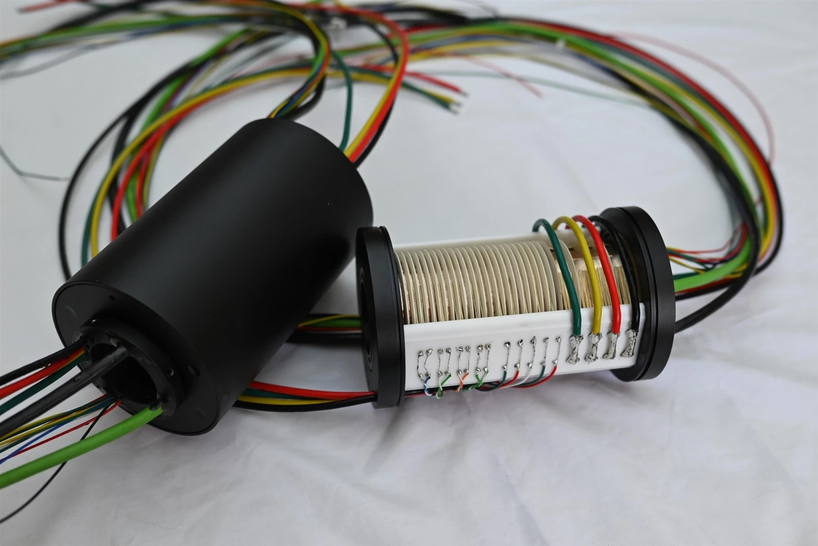
When an inspection robot fails in the field, the slip ring is often blamed because it sits at the rotating boundary. But the visible symptom may come from the slip ring, a connector, cable routing, motor EMI, power supply, moisture ingress, tether reel or mechanical alignment. Replacing parts without isolating the variable can hide the real cause and create repeat failures.
This guide is for post-failure troubleshooting. It is intentionally separate from ByTune's inspection robot selection guide and from pre-deployment validation. The goal is to move from a field symptom to a controlled diagnostic test.
Freeze the Field Symptom Before You Change Anything
Intermittent faults are easy to destroy during troubleshooting. Before disconnecting cables or replacing the slip ring, record:
- robot module that failed;
- whether the robot was moving or stationary;
- shaft angle or pan/tilt position if known;
- motor, light, heater or other load state;
- environmental condition;
- video/network/sensor symptom;
- whether power reset occurred;
- whether the fault recovered after stopping rotation;
- whether the fault repeats at the same position.
A repeatable event tied to angle, motion, motor load or moisture is far more useful than the statement "the camera sometimes drops out."
Use the Robot Module to Narrow the Fault Tree
| Module | Typical Symptom | First Areas to Check |
|---|---|---|
| Pan-tilt camera head | Video dropout, image artifacts, camera reboot | Camera power, video/data link, motor EMI, cable flex, rotary contact |
| Sensor turret | Intermittent readings, offset, false alarms | Sensor reference, shielding, contact variation, adjacent power circuits |
| Tether reel | Robot disconnects or loses power as reel turns | Slip ring, tether conductor, reel connector, strain relief, power drop |
| Manipulator joint | Stiction, inaccurate positioning, signal fault | Breakaway torque, cable preload, alignment, encoder path |
Video Dropouts: Decide Whether the Camera Lost Power or Data
When video disappears, first determine whether the camera remained powered. If the camera rebooted, the network or video loss may be a consequence of a power-path problem. If the camera stayed powered but the link failed, focus on the signal path.
For an IP or PoE camera, monitor:
- camera input voltage;
- link-up / link-down events;
- packet errors or retransmissions;
- application/video interruptions;
- motor activity at the time of the fault;
- rotational position.
For SDI or other coaxial video, check whether the receiver loses lock, whether artifacts appear before loss, and whether the fault repeats at a specific angle. A continuity meter cannot reveal all high-frequency channel problems.
Angle-Repeatable Faults Point to a Different Problem Than Random Faults
If a dropout or sensor spike appears at the same rotational position over repeated tests, investigate mechanisms that repeat with angle:
- localized contact-track condition;
- brush/contact alignment;
- cable or connector movement at one position;
- shaft runout or mechanical eccentricity;
- part of the tether or wire harness being pulled at one angle.
If the failure is random but strongly correlated with motor switching, the likely path is different: EMI, shared return current, supply disturbance or crosstalk should move higher on the list.
Separate Rotation From Motor EMI
Use four controlled states:
| State | Rotation | Motor / High-Current Load | Signal / Data |
|---|---|---|---|
| A | Stopped | Off | Active |
| B | Rotating | Off where possible | Active |
| C | Stopped | On | Active |
| D | Rotating | On | Active |
Interpretation:
- Failure only in B: prioritize motion/contact/cable effects.
- Failure in C and D: prioritize EMI, power quality or grounding.
- Failure only in D: investigate combined motion + electrical aggressor effects.
- Failure in all states: the slip ring may not be the dominant variable.
ByTune's electrical noise diagnosis guide provides a broader framework for contact resistance, EMI, crosstalk and grounding.
High Torque or Stiction: Check the Complete Mechanical Path
A camera head that moves poorly after slip-ring replacement may not have an electrical fault at all. Check:
- breakaway torque;
- running torque;
- cable twist or preload;
- connector strain;
- misalignment between rotor and stator;
- bearing or seal drag;
- foreign debris;
- temperature dependence.
Disconnecting the slip ring mechanically, where the assembly allows a safe comparison, can help distinguish component torque from the rest of the joint. Do not infer the cause from motor current alone because cable routing and alignment can also increase load.
Tether Reel Failures: Divide the Reel Into Electrical Sections
A tether reel contains several possible failure points: the stationary connector, slip ring, rotating connector, tether cable, strain relief and robot-side connector. Test the path section by section.
| Test Boundary | What It Helps Isolate |
|---|---|
| Stationary connector to slip-ring input | External stationary wiring |
| Across slip ring only | Rotary contact / internal wiring |
| Slip-ring output to tether cable end | Rotating connector, reel wiring and tether |
| Complete reel under rotation | Motion-dependent fault in the assembled system |
For power faults, measure voltage at the load while the robot draws representative current. For data faults, monitor the actual communication link during reel motion.
Moisture and Condensation: Inspect the Entire Environmental Boundary
A wet-field failure may occur even when the slip-ring housing appears intact. Water can enter through a connector, cable jacket damage, cable exit, gland or mating interface. Condensation can also form after temperature changes without direct immersion.
Inspect:
- housing joints and visible seal areas;
- cable exit and strain relief;
- connector shells and mating connectors;
- cable jacket damage;
- corrosion or residue;
- water tracks or droplets inside accessible cavities;
- changes in insulation or signal quality after exposure.
IEC 60529 defines ingress-protection classifications, but an IP code on one component does not describe the whole installed robot. ByTune's waterproof slip ring guide explains why terminations and connectors are part of the environmental system.
Sensor Drift: Distinguish Contact Variation From Reference Problems
Low-level sensors can drift because of contact variation, reference/ground problems, cable strain, temperature change or actual sensor behavior. Compare:
- sensor output with robot stationary versus rotating;
- output with nearby power circuits off versus on;
- same signal measured before and after the rotating interface where possible;
- different shaft positions;
- cold versus thermally stabilized operation.
If the signal changes only during rotation, inspect the rotary path and cable movement. If the same error appears while stationary whenever a drive switches, the dominant problem is likely not mechanical contact alone.
Build a Symptom-to-Test Matrix
| Field Symptom | Variable to Change First | Diagnostic Measurement |
|---|---|---|
| Camera reboots during rotation | Camera load / rotation | Rotating-side voltage and current during event |
| Ethernet drops at one angle | Shaft angle | Link/error counters correlated with angle |
| Video artifacts when pan motor accelerates | Motor state | Video/data error with motor on/off |
| Sensor spikes while rotating | Rotation and adjacent power | Sensor waveform/noise versus state matrix |
| Joint stalls after assembly | Mechanical load | Breakaway/running torque, cable preload, alignment |
| Reel loses communication after wet inspection | Environmental exposure | Connector/cable/slip-ring section test plus insulation/signal check |
When to Remove the Slip Ring for Bench Testing
Bench testing is useful after the system-level fault has been documented. Remove the component only when doing so will answer a specific question, such as whether an angle-dependent fault follows the slip ring when it is no longer connected to the robot's motors, tether or mounting structure.
Preserve the same cable and load conditions as much as practical. Otherwise a bench test can accidentally remove the real cause.
Use a Two-Stage Isolation Workflow
The first stage asks whether the fault belongs to the complete robot system or follows the rotary interface. The second stage divides the rotary interface into smaller electrical and mechanical boundaries.
- Reproduce the field symptom in the assembled robot. Preserve the original cable routing, connectors, loads and environment as closely as practical.
- Change one variable at a time. Stop rotation, disable one aggressor load, change direction or hold a known angle without changing several conditions simultaneously.
- Decide whether the fault follows motion, electrical load, angle, environment or time.
- Only then split the system. Test the slip ring, cable section, connector or power source independently when that split answers a specific hypothesis.
- Return to the assembled robot for final verification. A bench pass is not the final proof if the original problem occurred only in the installed system.
"No Fault Found" Is Not a Root Cause
If a removed slip ring passes a short bench continuity test, the investigation is not finished. The field fault may depend on angle, temperature, cable loading, moisture, motor switching or data traffic that was removed during the bench test.
When the component passes on the bench, document which original variables are no longer present and reintroduce the highest-value ones. For example, repeat the test with the original cable set, representative load current, controlled rotation speed and the same receiver or camera electronics. The goal is to explain why the field symptom occurred, not simply to obtain a passing component test.
Post-Repair Verification Must Reproduce the Original Failure Condition
| Original Failure | Repair May Include | Required Verification |
|---|---|---|
| Video drops at one angle | Connector/cable repair, slip-ring replacement or mechanical realignment | Multiple full rotations with video/error logging and angle correlation |
| Camera resets under load | Power-path or connector repair | Maximum representative camera/IR/heater load during rotation while monitoring voltage |
| High joint torque | Cable rerouting, alignment correction or component replacement | Breakaway and running torque in both directions after final assembly |
| Wet-environment communication loss | Seal, gland, connector or cable repair | Repeat the defined environmental exposure followed by the same communication test |
| Sensor noise with motor active | Grounding/shield/channel-routing correction | Repeat motor-off/motor-on state matrix with the same sensor acquisition setup |
Avoid Troubleshooting Actions That Destroy Evidence
- Do not replace the slip ring before recording whether the fault is angle-, load- or environment-dependent.
- Do not move every cable and connector at once; the fault may disappear without revealing the cause.
- Do not use continuity alone to clear a high-speed data or video channel.
- Do not interpret a camera reboot as a data-link failure until supply voltage is checked.
- Do not disconnect protective grounding as an improvised EMI test.
- Do not declare a repair complete until the original field condition has been reproduced without the fault.
Field Troubleshooting Record
A useful service report should include:
- robot and module identity;
- symptom and time of occurrence;
- motion state and shaft angle;
- active electrical loads;
- environmental condition;
- measurements taken;
- what variable was changed;
- whether the symptom followed that change;
- component or system changes made;
- final verification test.
This record helps separate one-off contamination or cable problems from repeatable design issues.
The Troubleshooting Rule
Do not start by asking whether the slip ring is bad. Start by asking what changes when the fault appears.
If the error follows rotation, inspect contact/cable/mechanical effects. If it follows motor switching, inspect EMI and power quality. If it follows one shaft angle, look for position-repeatable mechanisms. If it follows moisture exposure, inspect the complete sealing and connector path. If the robot loses both power and data, divide the tether reel into sections before replacing parts.
That variable-based method turns a difficult intermittent inspection-robot fault into a sequence of testable hypotheses.