

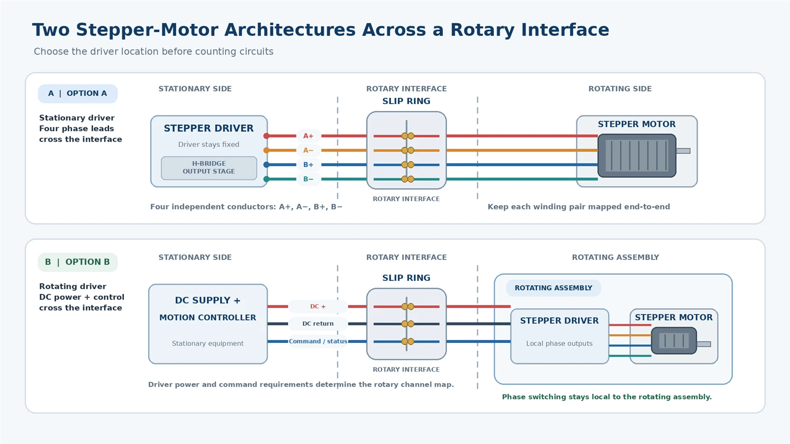
A stepper motor can be powered across a rotating interface, but the wiring decision starts with a question that a slip-ring circuit count cannot answer: is the motor driver on the stationary side or on the rotating side? If the driver remains stationary while the stepper motor travels with the rotating assembly, the motor phase leads pass through the slip ring. If the driver travels with the motor, the rotary interface usually carries DC supply power and the signals needed to command or communicate with that driver. Those are different electrical problems, and they should not be evaluated as interchangeable four-wire connections.
For a four-lead bipolar stepper, the first arrangement generally takes four separate conductor paths across the interface: two for phase A and two for phase B. The second arrangement can remove the chopper-driven phase outputs from the slip ring, but it introduces a rotating drive, its power and return paths, local supply stabilization, cooling, and a defined command link. Neither topology is automatically superior. The right one depends on the complete machine, the driver and motor documentation, the dynamic load, the electrical environment, and what can actually be tested.
This guide is about a stepper motor mounted on a rotating machine assembly and supplied through an external slip ring. It does not concern the wound-rotor induction machine also called a "slip-ring motor." Nor does it claim that every conventional ByTune circuit is suitable for chopper-driven motor phases. That compatibility has to be established for the chosen build under the actual drive waveform.
First locate the rotary boundary-not just the motor
A motor shaft turning does not, by itself, require an external electrical slip ring. In an ordinary stepper assembly the stator windings stay in a stationary motor body while the shaft rotates; the motor cables remain fixed. A slip ring becomes relevant when the entire motor or its driver is installed on a separate rotating platform, turret, inspection head, indexing drum, or other part that turns relative to the stationary controller.
Draw a boundary through that moving interface. Label which items stay stationary and which rotate: the controller, stepper driver, motor, limit switches, encoder, other sensors, power supply, machine ground, and any communications device. Then list each physical circuit that must cross. This prevents a common planning error: counting four motor wires before checking whether those four wires cross the boundary at all.
| Machine arrangement | What crosses the rotary interface? | First engineering question |
|---|---|---|
| Motor and driver both stationary; only motor shaft turns | Usually no external slip-ring path for the motor leads | Is an external rotating electrical interface actually required? |
| Driver stationary; motor mounted on rotating platform | Motor winding connections, ordinarily A+, A−, B+, B− for a four-lead bipolar motor | Can four rotary contacts carry the driver's actual switched phase current without harmful interruptions? |
| Driver and motor both on rotating platform | DC power and return, plus any command, feedback, interlock or communication channels that remain stationary | Can the rotating driver be powered, cooled, protected and commanded reliably? |
| Motor rotates with driver and local controller | Potentially power only, if commands and required feedback do not need a wired stationary link | What fault/status and emergency-stop information still needs to cross? |
Keep protective bonding and cable shields separate from normal current-return planning. A protective conductor must not silently become a substitute for a designed motor circuit. Any safety-related function requires its own system-level risk assessment and validated architecture; a generic slip ring should not be declared safety-rated because a signal was successfully passed once.
Architecture A: stationary driver, rotating stepper motor
With the driver fixed to the machine frame, each energized bipolar winding has an output conductor and a return conductor from the H-bridge. All four leads cross the rotary boundary. Because the driver reverses phase polarity, "return" here means the other terminal of the same phase-not a permanent shared DC ground. For typical four-wire bipolar wiring, each winding pair must remain intact from driver to motor.
Use the motor datasheet to identify the windings, not a color convention copied from another motor. A de-energized resistance or continuity check can help identify coil mates when the motor manufacturer allows that procedure, but it does not establish slip-ring current capacity, PWM behavior, or dynamic reliability. SparkFun's stepper driver wiring guide illustrates why winding pairs must be identified before connecting A and B outputs.
Phase assignment should be recorded at both ends of the slip ring as a one-to-one channel map. If a service technician later exchanges two lead positions, the symptoms may be a stalled motor, unexpected vibration, direction reversal, or loss of torque. Such behavior does not prove that the slip-ring contacts are defective. A wiring verification with the entire power stage disabled is the proper first separation.
| Example boundary channel | Stationary-side connection | Rotating-side connection | Evidence needed |
|---|---|---|---|
| R1 | Driver phase A terminal 1 | Motor phase A terminal 1 | Verified end-to-end mapping and rated dynamic current |
| R2 | Driver phase A terminal 2 | Motor phase A terminal 2 | Same phase pair; no unintended common return |
| R3 | Driver phase B terminal 1 | Motor phase B terminal 1 | Independent contact and matching pair identification |
| R4 | Driver phase B terminal 2 | Motor phase B terminal 2 | End-to-end polarity/order checked against the driver manual |
This is a functional mapping example, not a pinout for any ByTune model. Six- and eight-lead motors have alternative winding connections, and unipolar systems differ: their circuit count must be determined from the actual motor and drive architecture, not inferred from the word "stepper."
Why chopper-driven phase current is different from a simple DC load
A modern stepper driver commonly regulates winding current by switching its output bridge. The winding has inductance as well as resistance, so current does not respond instantly to applied voltage. The elementary relation V = L × di/dt describes the inductive component of voltage, and the full winding loop also includes resistive and driver effects. The driver alternates energization and recirculation paths to control phase current while the motor moves or holds position.
The resulting voltage waveform at a phase output is not necessarily a smooth DC value. Fast switching edges, cable capacitance, the layout of the two phase pairs and the driver's current-sensing scheme can interact. Analog Devices' stepper-motor cable guidance explains that capacitance between phase conductors can disturb chopper action and recommends appropriately paired and shielded wiring.
A slip ring adds moving contact interfaces and its own connecting conductors to that circuit. It does not perform the current regulation. Its behavior must be evaluated within the driver–cable–motor loop, especially if the winding circuit sees rapid transitions or the driver detects current using a small sense voltage. A successful stationary resistance check cannot establish that the driver will remain stable at every angle, speed, temperature and torque demand.
Do not treat the switching frequency as a slip-ring "signal bandwidth" specification without understanding the waveform and acceptance requirement. Contact stability, current rating, transient response, cable parasitics, grounding and driver susceptibility are separate dimensions. Novanta's stepper motor noise application note describes how chopping-related noise can couple into nearby low-level circuits.
Architecture B: rotating driver, DC supply through the slip ring
Moving the driver to the rotating payload changes the boundary. The slip ring no longer has to transmit the driver's phase-switching outputs, because the four motor leads are local to the rotating assembly. Instead, the power supply reaches the driver through dedicated positive and negative/return circuits, and the stationary system sends commands across whatever link the drive supports: step/direction, differential I/O, a specified serial link, fieldbus, or another validated interface.
This configuration can make the motor-side phase cables shorter and eliminate switching phase currents from the rotary contacts. But it should not be sold as a universal cure for electrical noise. The driver remains a switching load, the DC supply current may be pulsed, and the command link can still be sensitive to reference offsets, cable screening or noise from other channels. Local decoupling, transient limits and thermal design become important on the rotating assembly.
For power supplies, distinguish supply-side current from winding current. A chopper drive can circulate winding current through a bridge while drawing a different instantaneous or average current from its DC source. Therefore, adding two nominal phase currents is not a valid way to determine the slip-ring DC supply rating. Use the driver manufacturer's input-current information and measure the real worst-case machine demand. Novanta's DC power-supply sizing note explains why stepper supply sizing must consider motor and drive behavior together.
| Design item | Stationary driver | Rotating driver |
|---|---|---|
| Typical crossing circuits for four-wire bipolar motor | Four independently mapped phase conductors | Supply and return, plus required control/status paths |
| Switching waveform at rotating contact | H-bridge phase voltage/current behavior must be evaluated | DC bus with load pulses; phase switching remains local |
| Signal integrity challenge | Phase-pair coupling, contact disturbances, driver sensing | Command protocol, power noise, common-mode limits, data links |
| Rotating electronics | Motor, usually no rotating power stage | Motor and powered drive, with cooling and fault handling |
| Primary failure concern | Phase interruption while the driver is active | DC bus collapse or command loss causing drive reset/stall |
| Maintenance trade-off | Driver accessible on stationary frame | Driver may be harder to inspect or replace |
When deciding between layouts, also check mounting space, moving mass, vibration, heat dissipation, inertia and access for firmware or diagnostics. In a compact rotating head, moving the drive onto the rotor may create a mechanical or thermal penalty larger than the wiring benefit. An interface selection is complete only when these constraints are visible.
Choose contact ratings from measured electrical stress, not wire count
The current through a rotating contact depends on which architecture it serves. For the stationary-driver option, review each winding conductor under holding current, acceleration, high-speed operation, microstepping and any simultaneous two-phase energization states. For a rotating driver, characterize DC supply current including acceleration peaks, bus charging and other loads supplied by the same assembly. In either case, specify voltage class, insulation grouping, conductor gauge and the thermal environment.
A simplified resistive illustration is useful, provided its limits are explicit. Suppose, purely as a design example, that one entire external phase loop-two slip-ring paths plus leads and terminations-adds 0.30 Ω of resistance to a winding circuit. At an illustrative phase current of 1.5 A RMS, the added resistive dissipation is P = I²R = 1.5² × 0.30 = 0.675 W. That 0.675 W is distributed across every element included in the assumed 0.30 Ω; it is not a measured loss within a particular slip ring. Actual chopped current may change with the operating condition, so use the correct measured RMS value and path resistance for a defensible thermal result.
At a moment when current equals 1.5 A, that same added resistance produces 0.45 V of resistive drop. Whether the motor loses torque cannot be determined from that one number: available bus voltage, commanded speed, coil inductance, winding resistance and current regulation all matter. A useful test checks current tracking and motion performance with and without the rotary interface under equivalent operating conditions.
Dynamic contact disturbance is also important, but resistive loss and contact intermittency are not the same failure. A contact that shows a reasonable average voltage drop might still have short events that disturb an active drive. Conversely, a higher measured voltage drop may arise in external cables or terminals rather than the brush interface. Identify both the measurement boundary and the signal bandwidth before attributing a fault to the slip ring.
Phase-pair routing, shields and nearby signal channels
Keep the two conductors belonging to each motor phase identifiable and routed as a pair where the cable design permits. Do not interleave phase A and B randomly merely because channel numbers are consecutive. The contact geometry and exact conductor layout are supplier-specific, so an OEM should communicate the desired pair grouping to the slip-ring manufacturer rather than prescribe an unverified internal brush arrangement.
External shielding can help reduce emitted or coupled interference, but it does not make an arbitrary slip-ring contact into a high-frequency shield connection. A shield termination needs a deliberate chassis/grounding strategy compatible with the machine, the driver and the EMC design. Do not use the shield or protective earth as a phase conductor. If encoders, thermocouples, Ethernet or low-level sensors share the same rotary assembly, place their channel requirements in a separate section of the RFQ and evaluate simultaneous motor switching and signal operation.
Analog Devices notes that inter-phase coupling can disturb current chopping in some stepper systems. The practical design implication is to avoid treating all four motor leads as four unrelated low-frequency power wires. However, recommended cable construction varies by driver. The selected drive manual takes precedence over a generic cable rule.
For mixed power and data, the separate ByTune guide to power and data slip rings addresses the broader channel-separation question. This page keeps the narrow focus on stepper phase pairs and the location of the motor power stage.
Interruptions can be a driver-protection problem, not just a missed step
An energized motor winding stores energy. If a cable or contact opens abruptly while current is circulating, the driver can experience a voltage transient that depends on its output-stage design and current path. The risk is more serious than simply losing one command pulse. Several drive manufacturers explicitly caution against connecting or disconnecting a stepper motor while the driver is powered. For an example of the warning and its driver-specific scope, see the Pololu DRV8434S documentation.
A rotary contact is not a manually unplugged connector, and a momentary event at a moving interface is not proof that the same damage mechanism will always occur. The engineering concern is that a sufficiently severe intermittent opening or change in impedance under phase current can challenge the drive. Do not assume that every driver has identical transient immunity or that a general-purpose RC or flyback diode can be attached across a bipolar phase. The H-bridge reverses polarity and controls recirculation; ad hoc suppression may compromise drive operation.
Three responses belong in a safe development plan. First, do all channel mapping and resistance checks with energy isolated, following the driver instructions. Second, decide whether the driver and slip-ring supplier can approve the proposed motor-phase topology and define allowed interruptions. Third, if protection is needed, obtain a driver-approved design rather than installing arbitrary clamping parts at the motor leads.
When a drive faults, do not repeatedly reset and increase current without investigating. Capture fault codes, current commands, supply voltage and the timing of any rotation-dependent error. A faulty connector, wrong phase pairing, inadequate current limit, overloaded axis or unstable DC bus can mimic a slip-ring contact problem. A diagnosis must separate these mechanisms.
Where to measure: four boundaries tell different stories
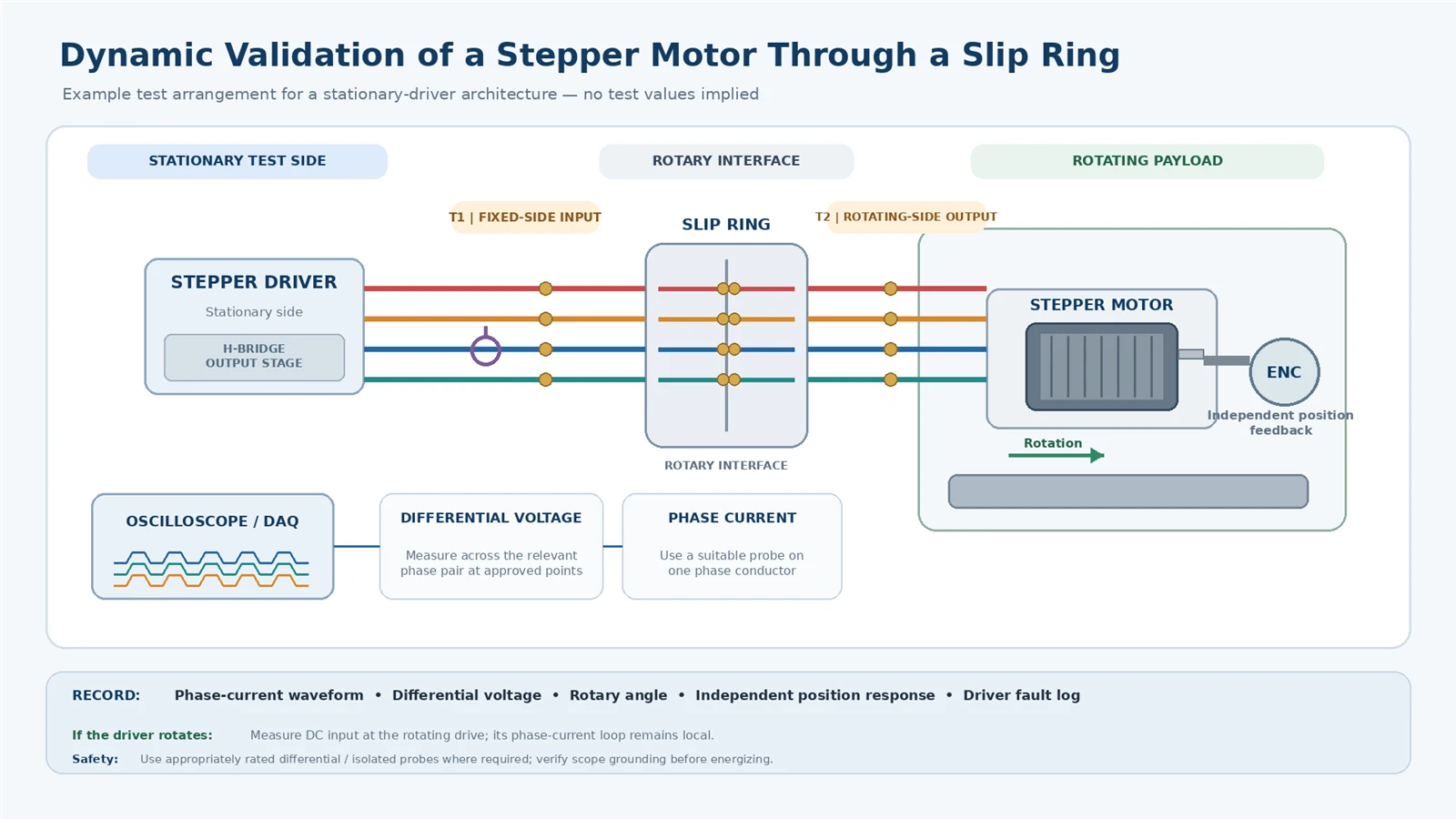
The objective of measurement is not to collect the greatest number of traces. It is to identify where an abnormal condition first appears. For a stationary-drive design, practical boundaries are the driver output, the fixed-side slip-ring lead, the rotating-side slip-ring lead, and the motor terminals. For a rotating-drive design, use the stationary DC source, both sides of the DC rotary path and the rotating drive input; then measure local motor phase currents using the drive manufacturer's permitted method.
| Measurement point | Information gained | Important limit |
|---|---|---|
| Driver command and fault/status record | Whether the intended motion and drive state were issued | A command record alone cannot prove the rotor actually moved |
| Stationary-side rotary-interface terminals | Signal/current waveform entering the crossing | Includes controller and preceding cable influences |
| Rotating-side terminals | Waveform after the crossing | Probe reference and isolated measurement safety must be planned |
| Motor-side phase current or rotating driver DC input | What the actual driven load receives | Choose the point that matches the selected architecture |
| Independent position or motion observation | Missed motion, stall or repeatability errors | Open-loop driver step counts do not verify physical position |
Comparing a pair of signals measured at different points is only meaningful when probe type, reference, bandwidth, sampling, time alignment and physical loading of the measurement are understood. Incorrect oscilloscope grounding on a switching H-bridge can cause equipment damage or a short circuit. Use appropriately rated differential or isolated measurement methods when required, and have qualified personnel approve the setup before energizing.
For contact-level methods rather than system phase-current performance, ByTune's static and dynamic contact-resistance guide explains why test points and measurement conditions matter. It does not replace a powered stepper drive qualification.
Build an acceptance test around real motor duty
Before the first powered rotation, freeze the test configuration: motor part number and winding connection, driver part number and firmware/settings, supply voltage, current limit, acceleration profile, mechanical load, slip-ring circuit map, contact rating evidence, cable lengths, cable shielding, and instrumentation. A result without this context cannot be generalized to another motor or driver.
Start with power isolated. Verify wire mapping, insulation and required bonding using test methods approved for the assembled system. Do not apply a generic dielectric test across connected driver electronics or sensor inputs. Then run a stationary baseline with the drive connected directly to the motor, where the machine design safely permits an equivalent setup. Repeat with the rotary interface installed and unchanged settings.
Qualify the complete operating envelope, not only an unloaded continuous spin. The machine's rotary axis speed is not the same as the stepper motor's commanded step rate; record both. The test cases should cover dwell with holding current, acceleration, reversal, normal travel, worst mechanical loading, and any simultaneous signal traffic.
| Test state | Measurements to retain | Decision question |
|---|---|---|
| Power-off verification | Phase-pair map, end-to-end path, insulation/bonding as specified | Are conductors connected correctly without cross-phase faults? |
| Drive enabled at standstill | Holding-current behavior, drive fault log, contact temperature baseline | Is holding stable without unexplained heating or nuisance faults? |
| Acceleration and reversal | Phase/DC bus current, speed, position, fault timing, supply sag | Does transient load expose a failure that steady running misses? |
| Rotary interface moving through full angle | Waveform events versus rotary angle and direction | Are disturbances position- or direction-dependent? |
| Worst validated speed and load | Torque or motion repeatability, current tracking, temperature | Does the complete axis retain the required operating margin? |
| Mixed-circuit operation | Control/data errors with motor chopping on and off | Do neighboring signal channels remain functional? |
| Thermally stabilized and repeated run | Temperature trend, fault count, motor position error, observed wear condition where relevant | Does the outcome remain acceptable beyond the first cold run? |
Acceptance thresholds must come from the driver, motor, machine function, risk analysis and approved supplier configuration. There is no universal slip-ring phase-current ripple limit, missed-step allowance or maximum contact-resistance fluctuation suitable for every stepper application. A functional acceptance statement should identify what was measured, under which conditions, and who approved the criteria.
If a controller reports no faults yet the machine loses position, verify mechanical motion independently. Open-loop steps are commands, not measurements of actual shaft position. A missed-step event can arise from inadequate torque, resonance, excessive acceleration or load change without any slip-ring failure. Conversely, a contact-induced disruption may be visible electrically before gross motion loss is observed.
Troubleshoot by changing one variable at a time
When an issue appears only after the rotary interface is introduced, first preserve a reproducible failing condition. Log the motion command, slip-ring angular position, driver status, phase or supply current, DC bus voltage and any neighboring channel activity. Then use safe A/B comparisons rather than immediately replacing the slip ring or increasing motor current.
| Observed behavior | Competing explanations | Useful distinguishing check |
|---|---|---|
| Motor vibrates but will not rotate | Wrong coil pairing; drive settings; mechanical obstruction; current regulation problem | Verify pair map de-energized, compare with direct-driver baseline and load condition |
| Driver faults during a particular platform angle | Moving contact disturbance; cable strain; connector motion; mechanical interference | Correlate angle with electrical events; mechanically isolate cable loads where safe |
| Stall on acceleration but not at steady speed | Torque margin; load inertia; DC bus sag; phase-current tracking | Compare acceleration profile and current/voltage before and after the rotary boundary |
| Nearby encoder or data link fails when motor energizes | Switching noise; ground/shield path; proximity to motor leads | Hold speed fixed; compare with chopper enabled/disabled and inspect cable layout |
| Works cold, faults after operation | Driver thermal limit; contact/terminal heating; cable or assembly expansion | Log actual component temperatures and repeat at matched load |
Broader coupling and grounding diagnosis belongs in ByTune's electrical noise troubleshooting guide. Here the distinct task is to determine whether the stepper motor architecture and dynamic motor-current path meet their own acceptance criteria.
Prepare the supplier brief before choosing a slip-ring model
Once the drive placement is fixed, a slip-ring supplier can evaluate a meaningful specification rather than a request for "four motor wires." Include the complete machine boundary, the motor and driver manufacturer/model, the selected architecture, the actual drive settings, relevant waveform/current data, and a performance target. Ask explicitly whether the proposed contacts have been evaluated for that electrical duty; do not infer approval from a generic low-voltage or continuous-current rating.
| Supplier input | Minimum useful information |
|---|---|
| Machine boundary and mechanics | What rotates and what stays fixed; mounting scheme; available bore, diameter and length; rotary-axis speed, duty and environment |
| Motor/driver topology | Driver location; motor winding type; phase map or DC supply/control channel map; driver model and configuration |
| Electrical loading | Measured per-path RMS/peak current as applicable; voltage waveform; duty; operating and transient limits |
| Other channels | Sensor, encoder, Ethernet or other protocol; shielding, bonding and cable/connector requirements |
| Failure and protection requirements | Permitted fault response; driver manufacturer precautions; safe shutdown procedure; service access |
| Acceptance evidence | Rotary speed/load profiles; measurement boundaries; test equipment; approved pass/fail criteria and record format |
For a system that needs nonstandard channel grouping, mechanical packaging or integrated power and signal paths, the ByTune custom slip ring page is an appropriate commercial starting point. It is a capability inquiry, not evidence that a specific existing ByTune part supports every stepper driver's PWM waveform.
The actionable rule is to choose the electrical architecture first, then qualify the rotating interface. Four mapped phase contacts may be the simpler mechanical solution when the driver must remain stationary. A rotating driver may reduce phase-current transmission through the slip ring, but demands local power, communication, cooling and protection. The correct decision is the one that remains stable under the installed machine's worst credible dynamic condition-and is supported by an approved channel map and recorded test evidence.