

Electrical noise in a rotating system is often blamed on the slip ring before the actual mechanism has been identified. That can lead to the wrong corrective action: replacing a contact assembly when the real problem is a ground loop, adding shielding when the fault is contact instability, or cleaning rings when a high-speed data channel is failing because of impedance or crosstalk.
A better method is to treat the slip ring as one part of the complete stationary-to-rotating electrical path. Define what crosses the rotary interface, observe exactly when the disturbance appears, then separate contact-related noise from conducted or radiated interference, channel-to-channel coupling, and grounding or shield-return problems.
This guide provides a practical diagnostic sequence for engineers working with sensor, encoder, control, analog, serial, Ethernet, video and mixed power-and-signal channels. It is not a replacement for a protocol-specific signal-integrity test or an EMC compliance test. Its purpose is to help isolate the dominant failure mechanism before design changes are made.
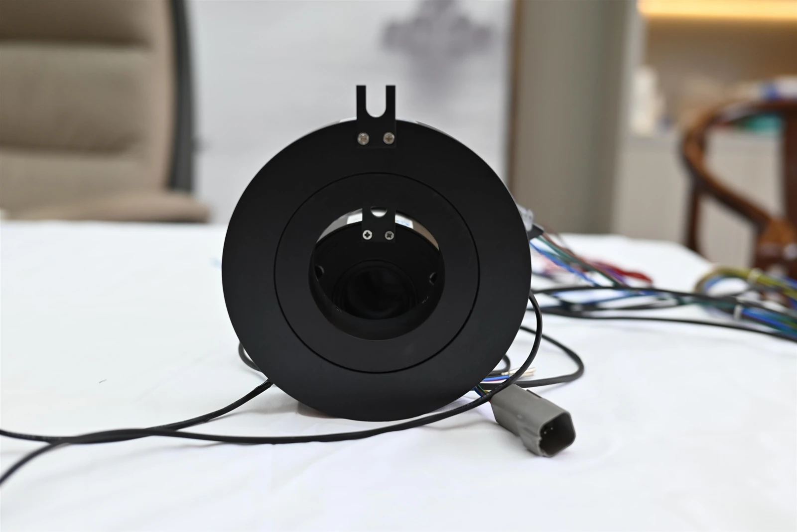
Start With the Complete Rotary Interface, Not the Slip Ring Alone
Before measuring noise, document the system boundary. Identify the stationary side, rotating side, the slip ring, cables, connectors, power supplies, drives, motors, shields, grounds and the receiving electronics. Then list every service crossing the interface: power, low-level analog, encoder feedback, serial communication, Ethernet, video, RF, protective earth and any shield or reference conductors.
The same symptom can come from different sources. A sensor reading that moves only during rotation may point to dynamic contact variation, cable strain or localized contamination. A disturbance that appears whenever a motor drive switches may indicate conducted or radiated interference even if the slip ring is stationary. Packet errors in Ethernet may occur with perfectly acceptable DC continuity if pair geometry, impedance, shield termination or crosstalk is poor.
That is why dynamic contact resistance, electrical noise and signal integrity should not be treated as interchangeable measurements.
Four Noise Mechanisms Engineers Should Separate
| Mechanism | Typical Clue | Most Useful Isolation Test |
|---|---|---|
| Contact-related noise | Disturbance changes with shaft angle, speed, vibration or rotation | Compare stationary and rotating traces; correlate events with angle and dynamic resistance |
| EMI / conducted or radiated interference | Noise follows motor, VFD, switching supply, relay or RF activity | Repeat the test with suspected aggressors off, then change separation, filtering or shielding one variable at a time |
| Crosstalk | One channel becomes noisy when an adjacent channel is energized or switches | Toggle neighboring circuits while the victim channel and rotation condition remain unchanged |
| Grounding / shield-return problem | Noise changes when equipment bonding, shield termination or reference connection changes | Map current-return and shield paths; test controlled termination arrangements without creating unsafe floating conditions |
1. Contact-Related Noise: Does the Problem Follow Rotation?
Sliding electrical contacts do not remain electrically identical at every angular position. Contact force, microscopic surface films, contamination, wear debris, runout, vibration and track condition can all influence the instantaneous electrical path. If resistance changes while current is flowing, the resulting voltage drop also changes with time.
The first diagnostic question is simple: does the disturbance exist when the system is stationary?
If the signal is clean while stopped but becomes unstable during rotation, repeat the test at more than one speed and in both directions if the mechanism allows it. Record the electrical waveform together with rotational position or a once-per-revolution marker whenever possible. A recurring event at the same angle is more useful than a single average resistance value because it can point to a localized track, runout, wiring or mechanical issue.
For low-resistance measurements, test-point location matters. End-to-end circuit resistance can include leads, terminations, internal conductors and the sliding interface. Define the measurement boundary before comparing values. The ByTune contact resistance testing guide explains the difference between static resistance, end-to-end resistance and dynamic resistance variation.
Contact-noise isolation sequence
- Capture the signal or voltage while the shaft is stationary.
- Rotate at the normal operating speed and capture the same quantity with the same bandwidth and filtering.
- Repeat at a lower speed to see whether the disturbance changes with motion.
- Correlate events with shaft angle, vibration or mechanical runout when possible.
- Inspect connectors, cable strain and external harness movement before opening the slip ring.
- If the evidence still points to the contact path, inspect contamination, wear, brush condition and track condition using the approved maintenance procedure.
2. EMI: Does the Noise Follow an Electrical Aggressor?
Motors, variable-frequency drives, switching power supplies, solenoids, contactors and RF transmitters can inject unwanted energy into sensitive channels. The coupling path may be conducted through power and return conductors, capacitively or inductively coupled between nearby wiring, or radiated into poorly protected cables and electronics.
The key diagnostic step is to separate motion from aggressor activity. Keep the slip ring condition unchanged and switch the suspected source on and off. If the disturbance tracks the aggressor rather than shaft position, investigate the complete EMC path before blaming the contact interface.
Shielding is not a universal fix. A shield only works as part of a defined return and bonding strategy, and high-frequency performance depends on geometry and termination. Filtering can also damage a legitimate high-speed signal if added without understanding the signal bandwidth. ByTune's existing EMI/RFI and signal-noise guide covers shielding, grounding and interference-control methods in more detail.
EMI isolation sequence
- Identify likely aggressors and their operating states.
- Capture the victim signal with the aggressor off and on.
- Repeat while the slip ring is stationary, then while rotating.
- Check whether changing cable separation or routing changes the result.
- Verify shield continuity and termination rather than assuming the shield is effective because a shielded cable is present.
- Use frequency-domain measurements when the source frequency or switching spectrum is relevant.
3. Crosstalk: Does Another Channel Trigger the Disturbance?
Crosstalk is unwanted coupling from one circuit into another. In a mixed slip ring, the aggressor may be a high-current switching circuit, a fast digital edge, a PWM motor lead, an encoder channel or another data pair. The victim may be a low-level analog sensor, control line or communication channel.
The most useful test is controlled channel activation. Hold speed, load and measurement settings constant. Then energize or switch one neighboring channel at a time while observing the victim. If the disturbance appears only when a specific aggressor is active, the evidence points toward channel coupling rather than random contact noise.
Do not diagnose crosstalk from conductor count alone. Coupling depends on geometry, spacing, return paths, shield structure, edge rate, frequency content and termination. High-speed interfaces also require their own physical-layer validation. A DC continuity or resistance test cannot prove that Ethernet, USB, video or another broadband channel will remain within its signal-integrity limits during rotation.
Crosstalk test matrix
| Test State | Rotation | Aggressor Channel | What the Result Suggests |
|---|---|---|---|
| A | Stopped | Off | Baseline receiver and instrumentation noise |
| B | Rotating | Off | Motion/contact contribution |
| C | Stopped | On | Electrical coupling independent of rotation |
| D | Rotating | On | Combined operating condition |
This four-state comparison is more informative than testing only the final combined condition because it shows which variable introduced the change.
4. Grounding and Shielding: Is the Return Path Defined?
Many apparent slip-ring noise problems are actually reference problems. Sensitive circuits need a predictable return path. Shields need an intentional termination strategy. Protective earth, chassis bonding, signal reference and cable shield are related but should not be treated as automatically interchangeable.
A common diagnostic mistake is to disconnect grounds randomly until the waveform looks cleaner. That can create unsafe conditions and can hide the real coupling path. Instead, draw the ground and shield topology first. Mark where the stationary and rotating structures are bonded, where signal returns flow, where cable shields terminate and whether a shield is interrupted by connectors or the rotary interface.
Then make controlled changes that preserve electrical safety. The diagnostic question is not simply "is it grounded?" but "where does current return, and what unwanted current is sharing that path?"
A Practical Symptom-to-Test Decision Table
| Observed Symptom | First Suspect | Next Test |
|---|---|---|
| Noise only while rotating | Contact variation, cable movement or mechanical influence | Stationary vs rotating trace; angle correlation; cable strain check |
| Noise starts when a VFD or motor switches | Conducted or radiated EMI | Aggressor on/off comparison with rotation held constant |
| One sensor channel fails when a nearby power channel is loaded | Crosstalk or shared return path | Adjacent-channel activation test; review routing and returns |
| Several channels show events at the same shaft angle | Shared mechanical/contact issue | Correlate electrical events with angle, runout and vibration |
| Data errors occur while DC resistance looks normal | Signal-integrity, impedance, shielding or crosstalk issue | Protocol/physical-layer test during rotation |
| Noise changes after shield or chassis connection changes | Ground/shield topology | Map return paths and verify shield continuity and termination |
Use Measurement Conditions That Can Be Reproduced
A noise value without test conditions is difficult to interpret. Record the rotational speed, direction, electrical load, signal source, receiver, cable and connector configuration, adjacent active circuits, temperature, measurement bandwidth, probe method, sample rate and filtering. For intermittent faults, also record test duration and the number of revolutions observed.
For a mixed power-and-data slip ring, test the signal channel with the real or representative power circuits active. A data link that passes in an otherwise unloaded assembly may behave differently when neighboring circuits carry switching current. ByTune's slip ring engineering guide recommends defining the exact signal, physical layer, shielding, ground reference, connector/cable type, nearby power circuits and dynamic acceptance test.
Diagnostic Acceptance Matrix
For prototype or troubleshooting work, agree on an acceptance matrix rather than a single "low noise" statement. The exact limits depend on the channel and system, but the test states can be defined consistently.
| Variable | Recommended States to Define |
|---|---|
| Rotation | Stopped, nominal speed, other critical speeds |
| Direction | Clockwise / counterclockwise where both are used |
| Electrical load | Idle, representative load, worst defined normal load |
| Adjacent circuits | Off, individually active, simultaneous operation |
| Environment | Relevant temperature or vibration condition if these are suspected |
| Measured output | Voltage/noise trace, dynamic resistance, packet errors, BER, encoder errors or application-specific result |
What to Put in an RFQ or Troubleshooting Report
Instead of requesting a "low-noise slip ring," describe the electrical architecture and the failure that must be prevented. A useful specification block should include:
- stationary-side and rotating-side equipment;
- every power, signal and data channel crossing the rotary interface;
- voltage, current, duty cycle and switching behavior for power channels;
- signal type, interface variant, data rate and physical-layer requirements;
- cable, connector, shield and ground-reference arrangement;
- adjacent high-current or switching circuits;
- rotation speed, direction and motion profile;
- the symptom already observed, if troubleshooting an existing system;
- measurement bandwidth and test method where relevant; and
- the dynamic acceptance test the finished assembly must pass.
This information makes it possible to separate a contact problem from an EMC, crosstalk or grounding problem and to test the complete rotating link under representative conditions.
The Main Diagnostic Rule
Do not start by asking how to "reduce slip ring noise." Start by asking what changes when the noise appears. Rotation points toward contact or mechanical effects. Aggressor switching points toward EMI. Neighboring-channel activity points toward crosstalk. Ground or shield changes point toward the return-path topology. High-speed data errors with normal DC measurements point toward signal-integrity requirements that need their own dynamic test.
Once the mechanism is identified, the corrective action becomes much more specific. That is the difference between replacing parts by trial and error and treating the rotating interface as an engineered electrical system.