

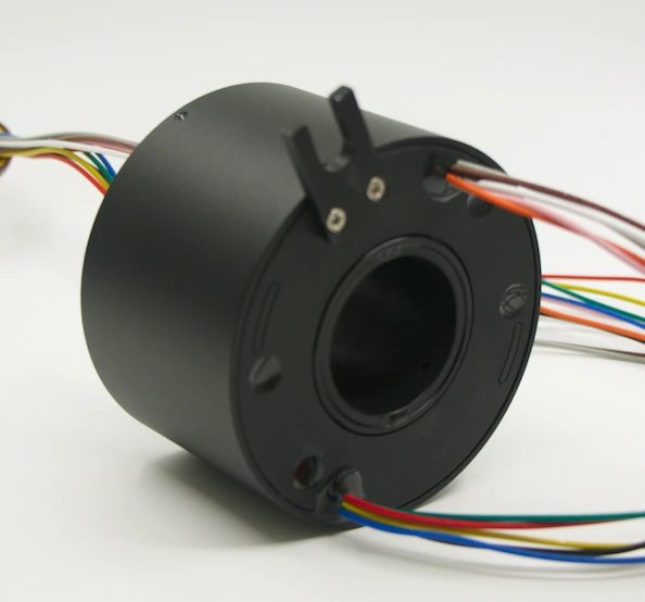
A filling machine slip ring should not be selected by product shape first. In a rotary filler, the better starting point is the rotating interface itself: what must cross from the stationary machine frame to the rotating carousel, at what electrical load or signal type, through what mechanical envelope, and under what cleaning and operating conditions?
That distinction matters because a filling machine may need more than electrical power. Depending on the architecture, the rotating section may also require control I/O, sensors, encoder feedback, industrial data, compressed air, vacuum, or process-related fluid services. The electrical slip ring, the fluid rotary joint, the wiring, connectors, hoses, mounting structure, and environmental protection therefore have to be treated as one rotary-interface system.
This guide focuses on that engineering task. It does not prescribe a single ByTune model for every filling machine. Model-level current, voltage, speed, IP rating, temperature, service life, signal performance, pressure, media compatibility, and certification must be confirmed against the actual drawing, datasheet, and test requirements for the project.
1. Map the Rotary Interface Before Choosing the Slip Ring Type
First identify the stationary side and the rotating side of the filler. Then list every service that crosses that boundary. A rotary carousel with filling valves, sensors, actuators, and local controls can have a very different interface from a simpler indexing machine, even when both are called filling machines.
| Service crossing the rotating interface | Questions to define before selection | Design consequence |
|---|---|---|
| Electrical power | How many circuits? What voltage and current does each circuit carry? What are the actual loads? | Determines circuit allocation, conductor size, insulation, heat load, and contact design. |
| Discrete or analog signals | What sensors, valve feedback, safety-related signals, or low-level analog signals cross the interface? | May require separation from higher-power circuits, shielding, and dynamic signal verification. |
| Industrial data | Ethernet, CAN, RS-485, encoder, or another interface? What physical layer, data rate, cable, connector, and shielding are required? | Requires signal-specific design rather than treating data as an ordinary electrical circuit. |
| Compressed air or vacuum | How many passages? What pressure, flow, port size, media, temperature, and leakage limit apply? | Usually requires a pneumatic rotary joint or an integrated electrical-pneumatic assembly. |
| Liquid or process media | What liquid is transferred? What are pressure, temperature, viscosity, chemical compatibility, cleaning method, and leakage limits? | Requires a suitable fluid rotary union; an electrical slip ring alone does not transfer process fluid. |
| Mechanical pass-through | Must a shaft, pipe, cable bundle, or central service remain on the machine axis? | Strongly influences bore size, outer diameter, length, mounting, and the choice between solid, through-bore, pancake, or custom structures. |
This interface map is the first engineering deliverable. It prevents a common selection error: choosing a familiar slip ring family and then trying to force the machine's services into it.
For the broader application context, see ByTune's industrial slip ring applications page. This article stays narrower and focuses specifically on how to define the rotary interface for filling machinery.
2. Build a Circuit Schedule, Not Just a Total Circuit Count
"Twelve circuits" is not a complete slip ring specification. A useful schedule identifies what each circuit actually does. Power for a motor or heater should not be treated as equivalent to a low-level sensor channel, an encoder pair, or an industrial network connection.
For each electrical path, record at least:
- circuit function;
- rated voltage;
- continuous and expected transient current;
- load type;
- signal or protocol type where applicable;
- required cable type and connector;
- shielding or grounding requirement;
- whether separation from power circuits is necessary.
On filling machinery, this matters because the rotating section can combine actuators and low-level feedback in a compact space. A design that is electrically adequate for power transmission can still be unsuitable for a sensitive measurement or communication channel if channel allocation, shielding, return paths, and cable geometry are not controlled.
3. Treat Ethernet, Fieldbus, Encoder, and Sensor Channels as Signal Systems
A label such as "Ethernet compatible" is not enough for engineering approval. The interface should be defined at the physical-layer level. For Ethernet, for example, the designer should specify the required Ethernet variant, data rate, cable construction, connector or termination, shielding concept, and whether power and data share the same assembly. Similar discipline applies to CAN, RS-485, encoders, video, and other differential or high-frequency signals.
The practical reason is simple: a rotating contact adds a dynamic electrical interface. Signal quality therefore has to be demonstrated while the assembly is rotating, with the actual cable arrangement and nearby power circuits represented as closely as practical.
A useful data-channel acceptance plan can include link establishment, error monitoring, packet-loss observation, signal-quality checks appropriate to the protocol, and repeated testing across the required speed range. Static continuity alone cannot demonstrate that a data channel will remain reliable in operation.
4. Decide Whether the Machine Needs a Slip Ring, a Rotary Union, or Both
Many filling machines combine electrical and non-electrical services. That does not mean every machine needs one fully integrated hybrid component, but it does mean the fluid and electrical requirements should be defined together before the architecture is frozen.
If the rotating carousel only needs power and electrical signals, an electrical slip ring may be sufficient. If it also needs compressed air, vacuum, water, cleaning media, product-related fluid, or another process medium, a rotary union or pneumatic/fluid rotary joint may be required. The electrical and fluid functions can be separate assemblies or integrated into a combined rotary-interface solution depending on the machine layout.
For any pneumatic or fluid path, define the actual medium, pressure, temperature, number of passages, port type and size, permissible leakage, seal compatibility, rotation speed, and cleaning exposure. Do not treat "pneumatic" and "hydraulic" as interchangeable labels; the media and sealing requirements are different.
ByTune's pneumatic slip ring page shows the product-family direction for combined electrical and media transmission. For a system-level specification workflow, see the slip ring and rotary union combination selection guide.
5. Freeze the Mechanical Envelope Before Comparing Product Families
The machine geometry often removes unsuitable slip ring types before electrical details do. Record the available axial length, maximum outer diameter, required center opening, mounting face, shaft relationship, orientation, cable exit direction, connector clearance, hose routing, and service access.
| Mechanical constraint | Architecture to investigate | Reason |
|---|---|---|
| A shaft, pipe, or central service must remain on the rotation axis | Through-bore architecture | The open center can preserve the required axial pass-through if the final bore and outer envelope both fit. |
| No center opening is required and radial/axial space is limited | Compact solid or capsule architecture | A central bore is unnecessary, so the package can focus on circuit density and envelope. |
| Axial height is tightly limited but radial space is available | Pancake or flat architecture | A flatter geometry may fit the machine, subject to the electrical and speed requirements. |
| Electrical, data, air, vacuum, or fluid requirements must share a constrained interface | Custom or hybrid architecture | The port layout, channel allocation, sealing, cables, and mounting may need to be engineered as one assembly. |
These are architecture cues, not automatic product recommendations. A through-bore design, for example, is not "better" simply because it has a center hole. It is useful only when that bore solves a real mechanical or service-routing requirement.
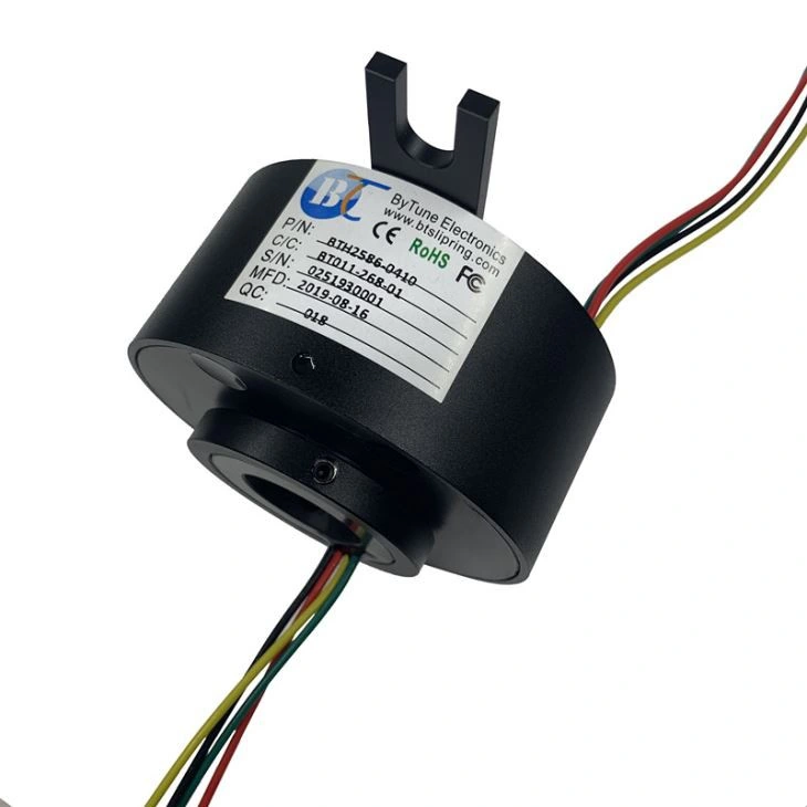
For machines that genuinely need a central pass-through, review the through-hole slip ring family after the required bore, circuits, speed, signals, and environment have been defined.
6. Specify Washdown as an Installed-System Requirement
Filling equipment may operate in dry industrial areas, wet-cleaned food-processing zones, beverage lines, pharmaceutical environments, or chemical-handling processes. "Washdown" therefore needs to be converted into specific exposure conditions rather than treated as a marketing label.
Define the cleaning method, water exposure, cleaning-agent chemistry, temperature, pressure, direction of spray, cleaning frequency, drainage, and whether connectors, cable exits, mounting interfaces, and adjacent components are exposed. The relevant IP rating is only one part of that evaluation.
IEC 60529 defines the IP Code as degrees of protection provided by enclosures. That means an IP rating should be interpreted for the rated enclosure and conditions, not automatically extended to every connector, cable termination, mounting interface, or the complete installed machine.
For food-processing equipment, hygienic design is also a separate system concern. EHEDG's guidance for wet-cleaned open food-processing environments addresses equipment design and integration from a hygienic perspective. A slip ring's ingress rating by itself does not establish hygienic suitability for a specific food zone.
For this reason, do not specify a filling-machine slip ring only as "IP65" or "washdown type." Define the actual cleaning exposure and verify the complete installed boundary.
7. Add Speed and Duty Cycle to the Same Specification
Rotational speed is not an isolated number. The same slip ring can experience very different electrical and mechanical stress depending on continuous versus intermittent rotation, acceleration and deceleration, operating hours, temperature, load, vibration, and maintenance conditions.
Record the normal operating speed, maximum speed, duty cycle, start-stop profile, expected operating hours, orientation, vibration or shock environment, and maintenance access. If service life is an important procurement requirement, ask for the conditions under which that life expectation is established. A revolution count without load, speed, environment, and maintenance context is not a complete life specification.
8. Validate the Rotary Interface Under Motion
The acceptance test should reproduce the functions that make the filling machine depend on the rotary interface. A static resistance or continuity check is useful, but it is not enough for a system carrying mixed power, sensor signals, data, and media.
| Function | Dynamic validation to plan | What a failure may reveal |
|---|---|---|
| Power circuits | Operate at representative load while rotating; monitor voltage drop, current, temperature rise, and abnormal interruption. | Undersized circuit, poor contact, excessive heating, wiring or termination problem. |
| Discrete/analog signals | Monitor the real signal during rotation across the speed range and near operating power loads. | Contact variation, noise coupling, grounding, shielding, or channel-allocation problem. |
| Ethernet or other data | Run the real link while rotating and monitor communication errors or loss of link under representative traffic. | Physical-layer mismatch, shielding/cable issue, dynamic contact problem, EMI coupling. |
| Pneumatic or vacuum passages | Rotate at operating speed while checking pressure stability, leakage, flow, and valve/actuator behavior. | Seal, port, hose-routing, leakage, or pressure-drop problem. |
| Fluid rotary joint | Test with the actual approved medium and representative pressure, temperature, speed, and cleaning cycle. | Material incompatibility, leakage, seal wear, thermal effect, or integration problem. |
| Washdown boundary | Validate the assembled installation, including cable exits, connectors, mounting interfaces, and adjacent protective features. | Ingress path outside the nominal slip ring housing. |
The goal is not to create the most complicated test plan possible. It is to prove the actual failure-sensitive functions of the filler while the rotary interface is operating in conditions that resemble the machine.
9. Prepare the RFQ Around the Machine, Not Around a Catalog Number
A useful filling-machine slip ring RFQ should give the supplier enough information to review the entire rotary boundary. Before requesting a model, prepare the following:
- machine type and a simple description of the rotating assembly;
- stationary-side and rotating-side definition;
- available outer diameter, axial length, and required center bore;
- mounting method, orientation, and cable/connector exit requirements;
- complete circuit schedule with voltage, current, and load type;
- signal and data details, including protocol, physical layer, cable, connector, shielding, and data rate where relevant;
- pneumatic, vacuum, or fluid media, passages, pressure, temperature, ports, leakage limit, and material compatibility requirements;
- normal and maximum speed plus duty cycle;
- temperature, vibration, dust, moisture, cleaning chemistry, washdown method, and other environmental exposure;
- required dynamic acceptance tests and any project-specific compliance requirements.
ByTune's custom slip ring request page already asks for many of these inputs, including dimensions, channels, voltage/current, signal details, pneumatic or hydraulic channels, pressure, port size, speed, temperature, and IP requirement. Supplying those inputs as a coherent machine-level specification makes it easier to evaluate whether a standard, modified, or fully custom solution is appropriate.
10. Use a System-First Selection Rule
The most reliable way to choose a slip ring for a filling machine is to delay the product-family decision until the rotary interface is defined.
First: map every service crossing the stationary-to-rotating boundary.
Second: separate power, low-level signals, data, air, vacuum, and fluid into their real engineering requirements.
Third: freeze the mechanical envelope, center-bore need, mounting, cleaning exposure, speed, and duty cycle.
Fourth: choose the electrical slip ring, rotary union, or hybrid architecture that satisfies those constraints.
Finally: validate the critical functions while the assembly is rotating under representative load and environmental conditions.
This approach prevents the slip ring from becoming a late-stage catalog choice and turns it into what it actually is: part of the filling machine's rotary power, control, data, and media architecture.