

A slip ring can be useful in a surgical robot only when a rotating joint needs electrical continuity that flexible cabling cannot provide reliably within the required motion envelope. The engineering problem is therefore not simply to find a "medical slip ring." It is to define the complete stationary-to-rotating interface inside the joint and prove that its mechanical and electrical behavior remains acceptable while the robot moves.
This matters because a precision robot joint can combine several constraints at the same location: limited radial or axial space, a central instrument or catheter passage, low available torque margin, motor or actuator power, encoder feedback, sensors, imaging or data channels, shielding and grounding, and repeated changes in direction. A design that passes a static continuity test can still create unacceptable rotational resistance, angle-dependent signal errors or communication problems after integration.
This guide focuses on that integration and validation task. It does not replace the broader robot slip ring selection guide, and it does not replace the commercial medical slip ring solutions page. It also does not establish medical-device regulatory compliance. Applicable safety, EMC, sterilization, biocompatibility and regulatory requirements must be defined at the complete device level by the equipment manufacturer.
First Decide Whether the Joint Actually Needs a Slip Ring
Not every surgical robot axis benefits from a slip ring. A limited-angle joint may be better served by a carefully routed flexible cable. The case becomes stronger when the joint needs continuous roll, repeated rotation that would otherwise wind the cable, or a compact rotary interface that must preserve a central passage for an instrument, catheter, shaft or other service.
Published surgical-robot architectures show why this distinction matters. One robotic surgical-system patent describes a slip ring integrated into a tool holder to transfer power and signals while a central passage remains aligned through the rotating assembly. The same architecture includes encoder electronics, motor-power electronics and a torque-sensing function around the rotating tool interface. See the published surgical robotics patent for an example of this system-level integration.
Academic work on MR-conditional interventional robotics has also demonstrated a hollow-shaft slip-ring arrangement that separates a catheter path from motor wiring while enabling continuous rotation. That example is useful because it shows that the slip ring cannot be evaluated independently from the mechanical path through the joint. See the UCL/IEEE robotic cardiac intervention study.
Build the Joint Interface Map Before Selecting an Architecture
Start by drawing the boundary between the stationary side and the rotating side. Then list every electrical and mechanical function that must cross or coexist with that boundary. Do not begin with circuit count.
| Joint Function | Typical Requirement to Define | Why It Changes Slip-Ring Integration |
|---|---|---|
| Motor or actuator power | Voltage, current per circuit, peak/inrush behavior, duty cycle | Affects conductor/contact sizing, thermal load and separation from sensitive channels |
| Encoder feedback | Encoder type, supply, signal format, frequency, cable and shield requirements | Position feedback can be sensitive to noise, grounding and channel coupling |
| Force / torque / position sensing | Signal level, reference, bandwidth and measurement sensitivity | Low-level measurements may require stronger separation and controlled return paths |
| Camera or imaging link | Exact video or data interface, data rate, cable, connector and physical-layer requirements | High-bandwidth channels cannot be treated as spare conductors |
| Control / communication | CAN, serial, Ethernet or other defined interface | Requires interface-specific dynamic validation |
| Electrosurgical energy, if applicable | System-specific power path, isolation and safety requirements | Must be treated as a separate engineered electrical function, not grouped with ordinary signal circuits |
| Central passage | Instrument, shaft, catheter, tube or cable bundle diameter plus clearance | Can determine whether a through-bore architecture is required |
Not every surgical robot uses all of these functions. The purpose of the map is to prevent assumptions. "Ten signals" is not a usable definition if those ten paths include an encoder pair, an analog sensor, a camera link and a communication bus.
Mechanical Integration Comes Before Product Type
Once the interface map is clear, define the mechanical envelope. Record the maximum outside diameter, available axial length, required center opening, mounting surface, rotor/stator orientation, allowable runout or misalignment, cable-exit direction, connector location and service access.
Three common architecture decisions illustrate the trade-off:
| Mechanical Constraint | Architecture to Evaluate | Main Integration Question |
|---|---|---|
| No central passage; very limited outside diameter | Capsule / miniature | Can the package still support the required circuits, signal paths, torque and connectors? |
| Instrument, shaft or other service must remain on-axis | Through-hole / through-bore | What clear bore is required after allowing for tolerances, routing and mechanical clearance? |
| Axial height is the dominant constraint | Pancake / flat | Is the additional radial envelope acceptable, and how will contact-track radius affect the dynamic design? |
These are architecture choices, not claims that a particular family is automatically suitable for surgery. Medical suitability, cleaning exposure, material requirements and any project-specific compliance requirement still need their own verification.
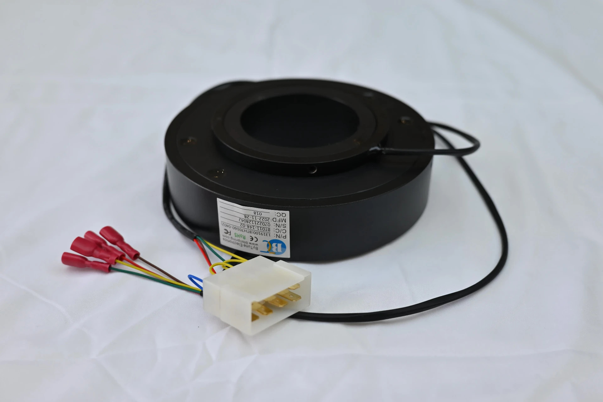
Low Torque Should Be Specified as a Joint Budget
"Low torque" is too vague for a precision joint. The useful question is how much rotational resistance the complete joint can tolerate and how much of that budget can be allocated to the slip ring.
At minimum, distinguish:
- starting or breakaway torque - the resistance that must be overcome when motion begins;
- running torque - the resistance during established rotation;
- torque variation - changes with angular position, direction, speed or time;
- system torque - the combined effect of the slip ring, bearings, seals, gearing, cable preload, connector routing and other joint elements.
This distinction matters because a robot can meet its average running-torque target and still exhibit an undesirable start-up peak or angle-dependent variation. The slip-ring specification should therefore state the torque quantities that matter to the motion-control design rather than requesting "minimal friction."
Recommended torque validation sequence
- Measure the joint without the slip ring if the architecture allows a meaningful baseline.
- Install the slip ring using the final mounting method and cable routing.
- Measure breakaway torque in both directions.
- Measure running torque over the intended speed range.
- Look for angle-repeatable peaks rather than relying only on an average value.
- Repeat after representative operating cycles if lifecycle drift is important to the system.
Exact acceptance limits must come from the robot's mechanical and control requirements. They should not be copied from a generic catalog value or from another robot platform.
Treat Every Signal Path as an Electrical Interface, Not a Wire Count
Surgical robot joints can combine actuator power with encoder, sensor, camera and communication channels. These functions have different electrical requirements, so channel allocation should be defined before the internal layout is finalized.
For low-level feedback, consider signal reference, shielding, return-current path and proximity to switching power. For Ethernet, video, USB or another high-speed interface, define the actual physical layer, cable construction, connector and required data performance. Electrical continuity alone does not establish protocol compatibility.
The design should also distinguish three different problems that are often described with the single word "noise":
- dynamic contact-resistance variation at the sliding interface;
- electromagnetic coupling from motors, drives or neighboring power circuits;
- crosstalk or grounding problems within the complete cable-to-slip-ring-to-cable path.
For the measurement boundary between static and dynamic resistance, see ByTune's slip ring contact resistance guide. For broader signal-path factors such as shielding, grounding and rotation-related instability, see the signal stability guide.
Define Cable, Connector and Grounding Interfaces With the Slip Ring
A suitable slip ring can still fail at system level if the surrounding interconnect is poorly integrated. Cable bending near the joint can add mechanical resistance. An unsupported connector can move under reversal. A shield that is terminated differently on the stationary and rotating sides can create an unexpected return path. A high-speed data channel can lose its intended geometry if the transition through the rotary assembly is treated as ordinary wiring.
Document:
- stationary-side cable type and length;
- rotating-side cable type and length;
- connector location and orientation;
- strain relief and allowable cable movement;
- shield termination at both sides;
- signal reference and chassis/bonding strategy;
- separation from motor or switching-power conductors;
- whether the slip ring sits inside or outside a cleaning, disinfection or sterile barrier.
The last item is a system-boundary question, not a reason to assume the slip ring itself must be sterilizable. If the component is exposed to a defined cleaning or sterilization process, material, seal, lubricant, cable and connector compatibility must be validated against that actual process.
Use a Dynamic Validation Matrix, Not a Single Bench Test
The acceptance plan should reproduce the variables that can change performance in the installed robot. A practical matrix separates those variables so a failure can be traced to motion, load, direction, adjacent channels or the physical-layer link.
| Test State | What to Operate | What to Measure | What It Helps Reveal |
|---|---|---|---|
| Stationary baseline | Joint stopped; representative electrical load | Signal baseline, resistance, link status, sensor output | Receiver/instrumentation baseline before motion is introduced |
| Low-speed rotation | Rotate below nominal speed | Torque, signal waveform, encoder errors, communication events | Contact- or angle-related behavior with limited dynamic effects |
| Nominal rotation | Normal speed and normal direction | Running torque plus application-specific electrical metrics | Normal operating performance |
| Direction reversal | Repeated clockwise/counter-clockwise motion if used | Breakaway peaks, signal interruptions, connector/cable movement | Reversal-sensitive mechanical and electrical faults |
| Representative power load | Motor/actuator circuits active | Sensitive signal channels and data link | EMI, shared-return and crosstalk problems |
| Adjacent-channel activation | Switch one aggressor channel at a time | Victim sensor/data channel | Channel-to-channel coupling |
| Extended cycling | Representative repeated motion | Torque trend, intermittent errors, temperature and electrical stability | Drift that does not appear in a short acceptance test |
The measured quantity should match the function. For an analog sensor, this may be noise, offset or drift. For an encoder, it may be error counts or position consistency. For a network link, it may be link stability, packet errors or a physical-layer measurement appropriate to the interface. For the joint itself, torque should be captured under the same cable routing and mounting conditions used in the robot.
Diagnose Failures by the Variable That Changes
| Observed Problem | First Engineering Question | Likely Areas to Investigate |
|---|---|---|
| Joint hesitates when motion begins | Is the peak mechanical resistance higher than the available torque margin? | Breakaway torque, cable preload, bearing/seal drag, alignment, mounting |
| Position feedback becomes unstable only during rotation | Does the error correlate with angle or speed? | Contact variation, encoder channel integrity, grounding, cable motion |
| Video or data errors occur when motors are active | Does the fault disappear when the power aggressor is removed? | Channel separation, shielding, return path, crosstalk, physical-layer integrity |
| Error repeats at the same shaft angle | Is the event mechanically or electrically angle-dependent? | Localized contact condition, runout, connector/cable movement, track-specific issue |
| Electrical performance is normal on the bench but fails in the assembled joint | What changed after installation? | Cable routing, grounding, connector loading, mechanical alignment, adjacent power circuits |
| Performance changes after cleaning or disinfection exposure | Was the actual exposure included in the environmental specification? | Materials, seals, cable jackets, connectors, residue or moisture ingress |
Surgical Robot Slip Ring Specification Block
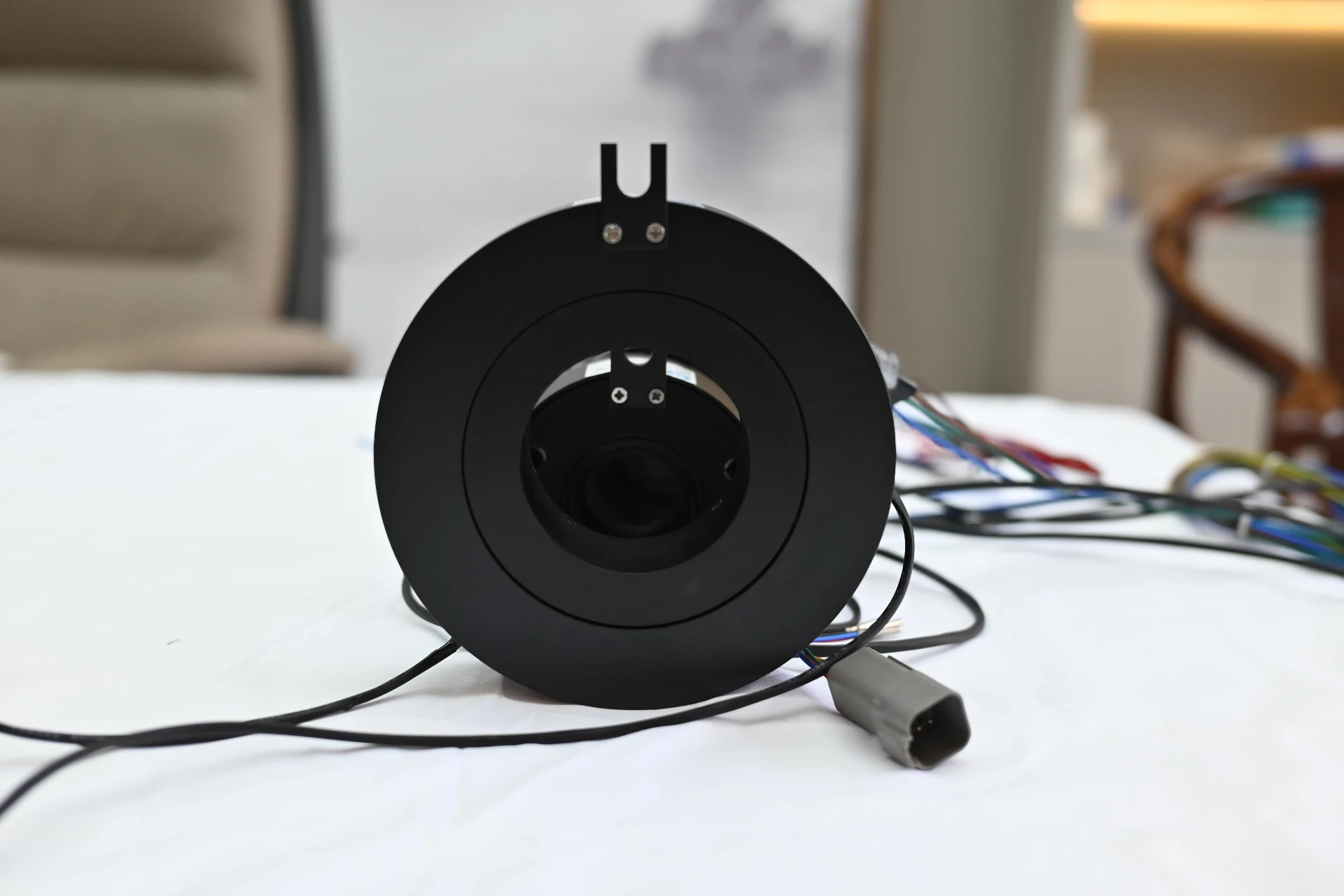
For a custom or application-specific rotary interface, the RFQ should describe the joint rather than only the desired slip-ring diameter.
- Joint function: base, arm joint, wrist, tool roll, instrument drive or other rotating interface.
- Motion: continuous rotation, limited rotation, oscillation or repeated reversal.
- Speed: normal and maximum operating speed plus reversal or acceleration profile where relevant.
- Mechanical envelope: maximum OD, axial length, mounting interface and connector clearance.
- Central passage: required clear bore and what must pass through it.
- Torque: allowable starting, running and variation limits if the joint has a defined torque budget.
- Power circuits: voltage, continuous current, peak/inrush condition and duty cycle for each circuit group.
- Sensor / encoder circuits: exact function, signal level, reference and cable/shield requirements.
- Data / video: exact interface, physical layer, data rate, cable and connector definition.
- Grounding / shielding: required chassis, shield and signal-reference arrangement.
- Environment: temperature, vibration, cleaning/disinfection exposure and other relevant conditions.
- Acceptance test: what must be measured while rotating, under what electrical loads and at which motion states.
If a standard product cannot satisfy the combined envelope, torque, channel and validation requirements, the project can move to a custom slip ring evaluation. Customization should solve a defined joint constraint; it should not substitute for an incomplete interface specification.
Integration Rule to Keep
For a surgical robot joint, the slip ring should be treated as part of the motion-control and signal-transmission system, not as an isolated connector. Define the joint first, preserve the required central passage and mechanical envelope, allocate a realistic torque budget, separate each electrical interface by function, and validate the completed rotating path under representative load and motion.
That approach creates a clear division of responsibility: the broad robot guide explains when and how robots use slip rings, the medical solution page supports application-level commercial requirements, and this integration guide focuses on the engineering work required inside a precision surgical-robot rotary joint.