

A rotating electrical connector transfers electrical power, control signals, sensor feedback, or communication data between a stationary structure and a rotating part of a machine. It keeps circuits connected without allowing fixed cables to twist, tighten, or repeatedly flex across the moving joint.
These connectors are used in packaging machines, cable reels, rotary tables, cranes, robots, wind turbines, antennas, test systems, medical equipment, and other machinery with powered or instrumented rotating assemblies. ByTune's introduction to the purpose of a slip ring provides additional background on this basic function.

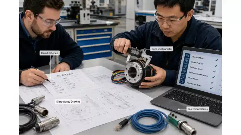
Choosing the right unit requires more than matching the number of wires. Each circuit, signal protocol, movement pattern, installation dimension, environmental exposure, maintenance requirement, and acceptance test can affect the final design. This guide explains how to organize those requirements before comparing standard and custom products.
Is a Rotating Electrical Connector the Same as a Slip Ring?
The terms are frequently used interchangeably. A slip ring is a rotary electrical interface that maintains electrical continuity between stationary and rotating sections. Suppliers may also use terms such as rotary electrical connector, collector ring, electrical rotary joint, rotary contact, or rotating electrical interface.
These names do not necessarily identify the underlying contact technology. Products described as brushed, brushless, non-contact, mercury-wetted, fiber-optic, or hybrid can operate in very different ways. A buyer should therefore look beyond the name and confirm:
- How power or signals cross the rotating interface
- Whether physical electrical contacts are involved
- Which components are subject to wear
- What inspection or maintenance is required
- How current capacity changes with speed and temperature
- How the stated signal and service-life performance was verified
For a broader comparison of available structures, see ByTune's guide to different types of slip rings.
Common Rotating Electrical Connector Types
| Connector Type | When It Is Commonly Considered | Key Limitation to Check |
|---|---|---|
| Capsule or end-of-shaft | The shaft end is open, radial space is limited, and the circuit count is moderate. | Total length, outside diameter, current per circuit, cable exit, and connector clearance. |
| Through-bore or through-hole | A shaft, tube, hydraulic line, drive component, or cable bundle must pass through the center. | Bore size and outside diameter must both fit the machine layout. |
| Pancake or flat | Axial height is severely limited and more radial space is available. | The reduced height may require a substantially larger diameter. |
| High-current or high-voltage | The rotating section includes welding circuits, heaters, motors, charging equipment, or industrial power transfer. | High current and high voltage are separate design requirements. |
| High-speed | The assembly operates at an elevated rotational speed or requires precise balance. | Heat, wear, vibration, bearing load, balance, and signal behavior must be reviewed together. |
| Signal and data | The machine carries encoders, sensors, CAN, Ethernet, USB, video, or another communication protocol. | Continuity alone does not prove reliable protocol performance. |
| Electrical-fluid hybrid | Electrical circuits must share the axis with compressed air, hydraulic fluid, vacuum, coolant, or process media. | The electrical and fluid sections need separate specifications and validation. |

Capsule and End-of-Shaft Designs
Compact designs are commonly used at the end of a rotating axis in automation equipment, camera systems, small turntables, robotics, laboratory equipment, and packaging machines. The available capsule slip ring range illustrates typical compact product architectures.
An end-of-shaft design is not automatically suitable just because the required circuit count is low. The engineer must also check cable bend space, total axial length, connector access, installation alignment, torque, and the current required by each circuit.
Through-Bore Designs
A through-hole slip ring has an opening through its center. This allows it to fit around an existing shaft, tube, central drive component, hydraulic passage, or cable bundle.
Bore diameter should never be evaluated by itself. Increasing the central opening normally affects the overall housing diameter and may also affect the number of available circuits, current capacity, mounting arrangement, and cable exits. A dimensioned machine drawing is therefore more useful than a bore requirement alone.
Pancake Designs
A pancake slip ring arranges its conductive paths in a flat form. It can solve an axial-height problem, but it does not necessarily reduce the total installation volume. The designer exchanges axial length for radial diameter and may also need to review shielding, track spacing, mounting accuracy, and environmental protection.
High-Current and High-Voltage Designs
High-current applications include rotary welding systems, heaters, large motors, charging equipment, and heavy industrial power transfer. The specification should state the continuous and peak current of every circuit, duty cycle, operating voltage, ambient temperature, rotational speed, grounding arrangement, and acceptable temperature rise.
A product capable of carrying high current is not automatically suitable for high voltage. High-current selection focuses heavily on conductor size, contact resistance, heat generation, and thermal management. High-voltage selection also requires suitable insulation, spacing, creepage, clearance, and protection against electrical breakdown. ByTune's overview of high-current slip rings provides a related technical path.
High-Speed Designs
Rotational speed can affect contact behavior, bearing load, mechanical balance, temperature, wear, and signal stability. A connector that briefly reaches a high speed during a test cycle does not have the same duty as one that runs continuously at that speed.
The specification should distinguish normal speed, maximum speed, duration at maximum speed, acceleration, direction changes, operating hours, and balancing requirements. The article on high-speed slip rings discusses this product category in more detail.
Electrical and Fluid Hybrid Designs
Some machines must transfer electrical circuits together with compressed air, hydraulic fluid, coolant, vacuum, or another process medium. A hybrid assembly can reduce the number of separate rotary components, but it does not eliminate the need to specify each system independently.
Electrical requirements should include the circuit schedule and signal information. Fluid requirements should include the medium, pressure, flow, number of passages, fitting type, temperature, material compatibility, and allowable leakage. ByTune's pneumatic slip ring range provides examples of fluid and hybrid rotary interfaces.
Application-to-Connector Selection Matrix
| Application | Typical Rotating Requirements | Connector Structure to Evaluate |
|---|---|---|
| Packaging turntable | Motor power, heaters, valves, sensors, Ethernet, and pneumatic passages | Through-bore electrical-fluid hybrid |
| Cable reel or winch | Power, brake circuits, limit switches, encoder feedback, and repeated drum rotation | End-of-shaft, through-bore, or large separate assembly |
| Industrial robot | Compact installation, servo power, encoders, fieldbus, and repeated movement | Capsule, through-bore, or custom signal-qualified assembly |
| Wind turbine | Power, pitch controls, sensors, communication, vibration, and long service intervals | Large through-bore or customized multi-circuit connector |
| Rotary welding fixture | High current, low resistance, heat control, and grounding | Dedicated high-current rotary transfer device |
| Antenna or radar platform | Power, control, Ethernet, RF, or fiber-optic transmission | Mixed electrical, high-frequency, or fiber-optic rotary interface |
| Inspection or test equipment | Low-noise measurements, controlled impedance, repeatability, and traceability | Signal-qualified multi-channel or custom assembly |
This table is an initial screening tool, not a model-selection chart. Machines in the same category can have different current, data, speed, environmental, and dimensional requirements.
Six Engineering Decisions That Control Connector Selection
1. Define the Electrical Load Circuit by Circuit
Do not begin with a total current value or wire count. Build a circuit schedule showing the purpose, voltage, continuous current, peak or inrush current, AC or DC operation, duty cycle, grounding, wire size, and connected load for every circuit.
A motor, heater, brake, solenoid, encoder, and data channel cannot be treated as equivalent contacts. A twenty-four-channel connector carrying only control signals is a different design from a twenty-four-channel connector carrying motor power, heaters, sensors, and Ethernet.
Contact resistance matters because every conducting interface produces some voltage drop and heat. For higher-current circuits, the supplier should explain how resistance and temperature rise are evaluated under the specified load and rotation. Several smaller contacts should not be paralleled unless the manufacturer has approved the arrangement, because the current may not divide evenly between contacts.
2. Name the Signal and Define How It Will Be Tested
"Signal circuit" is not a complete specification. A switch input, thermocouple, encoder, CAN network, Ethernet link, USB connection, and video channel have different electrical requirements.
For each sensitive or data circuit, identify:
- The exact signal or protocol
- Data rate
- Cable and connector type
- Characteristic impedance where applicable
- Shielding and grounding arrangement
- Acceptable noise or error
- The required test while the connector is rotating
Ethernet is standardized through the IEEE 802.3 Working Group, but stating "Ethernet" alone still does not define the complete rotating link. The Ethernet type, cable geometry, connector, channel separation, grounding, and dynamic test conditions should be agreed before ordering.
High-speed data can be affected by impedance discontinuity, shielding gaps, crosstalk, electromagnetic interference, and connector transitions. A continuity test confirms that a conductor is not open; it does not confirm reliable packet transmission. ByTune's Ethernet slip ring guide provides additional application context.
3. Describe the Real Motion Profile
State whether movement is continuous rotation or limited-angle oscillation. Include normal speed, maximum speed, time at maximum speed, direction changes, starts and stops, acceleration, daily operating time, and the expected service period.
These conditions should be reviewed together rather than reduced to a single maximum-rpm value. Continuous operation places greater emphasis on temperature and long-term wear, while repeated reversing movement can produce a different contact and cable-loading pattern.
4. Freeze the Mechanical Interface Before Selecting a Model
Provide a dimensioned drawing showing:
- Required bore
- Maximum outside diameter
- Maximum axial length
- Shaft dimensions
- Flange or mounting holes
- Stationary and rotating sides
- Anti-rotation point
- Cable exit direction
- Connector and service clearance
- Nearby moving parts
The connector should not depend on unsupported wires to restrain the stationary side. Misalignment, rigid anti-rotation mounting, poor strain relief, or insufficient cable clearance can place unintended loads on the assembly. The manufacturer's installation instructions should be reviewed before the machine design is finalized.
5. Define the Environment, Not Just an IP Number
Describe the actual exposure: fine dust, large debris, rain, direct water jets, washdown, temporary immersion, condensation, oil, salt, fertilizer, cleaning chemicals, corrosion, UV exposure, and installation inside another enclosure.
The IEC explanation of IP ratings states that IEC 60529 classifies enclosure protection against intrusion by dust and liquids. An IP rating is useful, but it does not by itself define chemical compatibility, corrosion resistance, condensation control, cable-gland sealing, connector protection, or installation orientation.
The selected protection should apply to the complete installed assembly, including external connectors, flying leads, cable entries, and surrounding covers. ByTune's guide to slip ring IP ratings can support the initial environmental review.
6. Agree on Service Life, Compliance, and Acceptance Tests
Service-life claims are meaningful only when the operating conditions are defined. Compare products under the intended current, speed, temperature, duty cycle, environment, vibration, and maintenance schedule.
Ask which components are subject to wear, what inspection is required, whether brushes or bearings are serviceable, which conditions shorten life, and how the unit can be replaced after installation.
Compliance requirements also depend on the exact product and target market. The European Commission explains that the RoHS Directive restricts certain hazardous substances in electrical and electronic equipment. A buyer should confirm whether the requested declaration applies to the exact connector configuration rather than assuming that one document covers an entire product family.
Acceptance testing should match the application risk. It may include:
- Continuity and insulation checks
- Static and dynamic resistance measurements
- Temperature-rise testing under load
- Rotational testing at the specified speed and duty cycle
- Signal or protocol testing during rotation
- Dimensional inspection
- Environmental testing where required
- Customer-specific first-article inspection
ByTune's guide on how to test a slip ring outlines common inspection and electrical test considerations.
Worked Example: Specifying a Rotating Packaging Table
The following is a hypothetical example intended to demonstrate the selection process.
A packaging machine has a continuously rotating table carrying one small motor, two heaters, several pneumatic valves, position sensors, an encoder, an Industrial Ethernet device, and two compressed-air passages.
A request for "a twenty-four-channel slip ring with two air ports" would be incomplete. It does not show which channels carry heater current, which circuit has motor inrush current, whether the encoder is sensitive to noise, or how the Ethernet link will be tested.
Electrical Load
The motor and each heater should be listed separately with voltage, continuous current, peak current, duty cycle, and wire size. Valve and sensor circuits should not be grouped with the heater circuits simply to obtain one total current figure.
Signals and Data
The specification should identify the encoder type and the exact Ethernet protocol. Cable, connector, shielding, grounding, channel separation, and dynamic communication tests should be defined before approval.
Pneumatic Requirements
The number of passages, operating pressure, peak pressure, flow, air quality, fitting type, temperature, and allowable leakage should be listed independently from the electrical schedule.
Mechanical and Environmental Requirements
The supplier should receive the required bore, maximum diameter, axial space, table speed, cable direction, cleaning method, ambient temperature, and maintenance-access drawing.
With this information, the buyer can compare a standard through-bore hybrid platform, a modified-standard assembly, and a fully custom connector on the same technical basis.
Standard, Modified-Standard, or Fully Custom?
| Option | Appropriate When | Primary Trade-Off |
|---|---|---|
| Standard connector | Circuits, dimensions, speed, environment, cables, and connections match an existing product. | Lowest design effort, but limited flexibility. |
| Modified-standard connector | A proven platform fits, but cable length, connectors, sealing, or circuit arrangement needs adjustment. | Reduces development work, but changes remain limited by the original platform. |
| Fully custom connector | The project has unusual dimensions, high current, high-speed data, hybrid media, severe conditions, or special testing. | Requires additional engineering, drawings, prototype review, and validation. |
A custom design is not automatically superior. A proven standard platform can reduce technical risk, cost, and lead time when it satisfies the application. The comparison of standard and custom slip rings provides a useful decision framework.
When no existing platform meets a critical electrical, signal, mechanical, environmental, or fluid requirement, the project should move to custom slip ring engineering.
Common Selection Mistakes
| Mistake | Why It Creates Risk | Better Approach |
|---|---|---|
| Selecting by wire count | It treats power, sensors, encoders, and data as equivalent circuits. | Create a circuit schedule. |
| Using total current | It hides the continuous and peak requirement of each load. | Rate every circuit separately. |
| Calling every non-power circuit a signal | Different signals require different cable, shielding, impedance, and tests. | Name the exact signal and protocol. |
| Requesting a waterproof product | The term does not define water jets, immersion, condensation, connectors, chemicals, or corrosion. | Describe the actual environment. |
| Copying a part number from another machine | Similar equipment may have different loads, bore sizes, cables, speeds, and exposure. | Compare complete specifications and drawings. |
| Accepting a continuity test for data circuits | Continuity does not prove reliable protocol operation during rotation. | Agree on dynamic signal acceptance criteria. |
| Ignoring installation access | A suitable connector can still cause downtime if it cannot be inspected or replaced. | Review installation and service before freezing the layout. |
RFQ and Supplier Review Checklist
A complete request for quotation should allow suppliers to evaluate the same application rather than quote the closest catalog model.
- Machine and application description
- Identification of the stationary and rotating sides
- Complete electrical circuit schedule
- Continuous and peak current for each power circuit
- Exact sensor, encoder, communication, video, or data protocols
- Cable, connector, shielding, grounding, and impedance requirements
- Continuous rotation or oscillation
- Normal and maximum speed
- Duty cycle and expected service period
- Required bore, maximum diameter, length, and mounting drawing
- Cable exits, connector clearance, and anti-rotation arrangement
- Temperature, vibration, and shock conditions
- Dust, water, washdown, chemicals, corrosion, and UV exposure
- Pneumatic, hydraulic, vacuum, or coolant requirements
- Required declarations, inspection reports, and traceability
- Electrical, rotational, signal, and environmental acceptance tests
- Prototype quantity, annual quantity, and project schedule
- Installation photographs or dimensioned drawings
Before approving a proposal, confirm which standard platform is being used, which requirements require modification, what maintenance is expected, which tests apply to the exact configuration, and whether cables and connectors are included in the environmental claim.
Once the application information is complete, submit it through the ByTune contact and quotation page for technical review.
FAQ
Q: Can A Rotating Electrical Connector Carry Power And Ethernet Together?
A: Yes, when the assembly is designed for the specified power circuits and exact Ethernet requirements. Cable geometry, shielding, grounding, impedance, connector type, separation from power channels, and dynamic communication tests should be confirmed.
Q: What Is The Difference Between A Slip Ring And A Rotary Union?
A: A slip ring transfers electrical power or signals across a rotating interface. A rotary union transfers media such as compressed air, hydraulic fluid, coolant, or vacuum. Both functions can be integrated into a hybrid assembly.
Q: When Is A Through-Bore Connector Required?
A: It is commonly considered when a shaft, tube, drive component, cable bundle, or fluid passage must pass through the center of the connector. The bore, outside diameter, length, speed, circuits, and mounting method must still be evaluated together.
Q: Are Brushless Rotating Connectors Always Maintenance-Free?
A: No universal conclusion can be made from the term "brushless." Different products may use different transmission technologies, and bearings, seals, cables, fluid sections, or other components may still require inspection or replacement.
Q: How Should Service Life Be Compared?
A: Compare service-life claims only under defined current, speed, temperature, duty cycle, vibration, environment, and maintenance conditions. A headline life figure without operating conditions is not sufficient for an engineering comparison.
Q: When Should A Custom Connector Be Used?
A: A custom design is appropriate when no standard or modified-standard platform can meet a critical electrical, signal, mechanical, environmental, fluid, compliance, or testing requirement.
Final Recommendation
The best rotating electrical connector is not necessarily the model with the highest channel count or the strongest performance claim. It is the configuration whose electrical load, signal integrity, motion, mechanical fit, environmental protection, maintenance plan, and acceptance tests match the real machine.
Build the circuit schedule first. Then define the signals, movement, dimensions, environment, service expectations, and tests. This sequence makes it easier to compare standard and custom options, reduces quotation delays, and exposes technical conflicts before the connector is installed.