

A rotating pick-and-place gripper may hold a workpiece perfectly while stopped, then lose vacuum during indexing, reversing or continuous rotation. That symptom does not identify the rotary union as the failed part. The same result can come from a weak vacuum source, a restricted hose, a leaking fitting, a valve that changes state too early, a worn suction cup, or acceleration beyond the gripper's holding margin.
The useful question is not simply "Is the rotary joint leaking?" It is: at which point in the pneumatic path does vacuum performance first depart from the known-good condition, and under what motion and load does the deviation appear? This guide gives maintenance teams and machine builders a method for answering that question with section-by-section measurements, controlled isolation and rotation-dependent acceptance tests.
The focus here is vacuum-grip troubleshooting, not product selection. For architecture and initial sizing, see ByTune's slip ring and rotary union specification guide. When electrical power or signals must also cross the rotating axis, the pneumatic and hybrid rotary-interface product family is a relevant starting point, subject to a project-specific vacuum design and validation.
For a real product reference, ByTune's electrical and pneumatic hybrid application example identifies its BTA056-0401 pneumatic rotary module and shows a product photograph. That illustration helps identify the type of rotating media interface, but it does not establish the leakage behavior or suitability of a particular unit in the gripper being investigated.
First, Locate the Rotating Boundary and the Vacuum Source
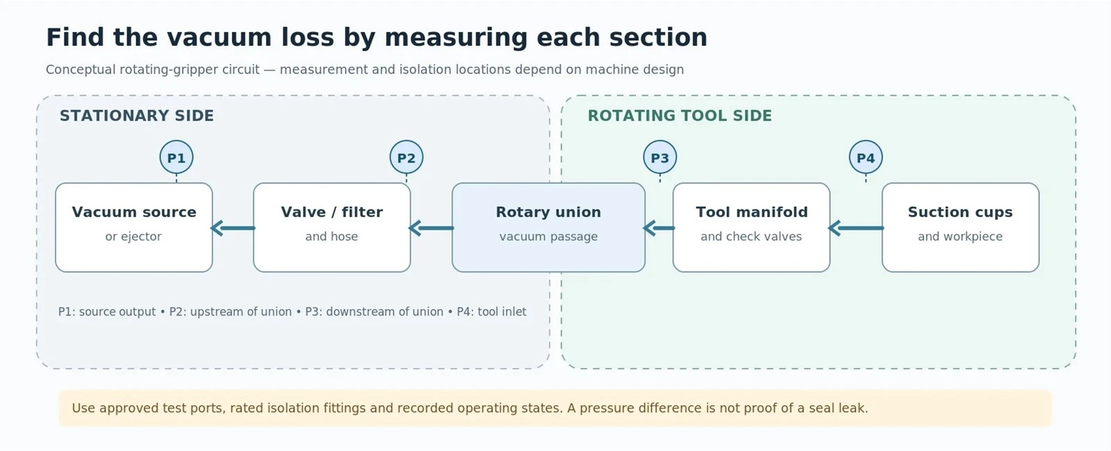
Before loosening any connection, draw the actual vacuum circuit. In one common architecture the source, switching valve and filter remain stationary. The vacuum passage crosses a rotary union and feeds a rotating tool manifold and suction cups. In another architecture the generator rotates with the tool and only compressed air or electrical control crosses the axis. Those are not the same diagnosis. If the generator rotates with the gripper, there may be no vacuum passage in the rotary interface at all.
| System element | Question to resolve | Why it matters |
|---|---|---|
| Stationary structure | Where are the compressor, ejector or vacuum pump, valves and regulators? | Sets the reference measurements for supply capability. |
| Rotating structure | Which hoses, manifold, check valves and cups move with the gripper? | Reveals flexing, acceleration loads and tool-side leak sites. |
| Rotary interface | Does the machine cross vacuum, compressed air, electrical power, feedback or a combination? | Prevents a pneumatic fault from being attributed to an electrical slip ring. |
| Workpiece | Is the surface smooth, rough, porous, oily, wet, curved or varying between batches? | A grip can leak at the cup even when all pipes and seals are sound. |
Use the machine drawing to note the stationary and rotating sides, hose support, permitted bend radii, union mounting, port orientation and any mechanical side load. A vacuum rotary union and an electrical slip ring perform different functions; the general distinction is explained in ByTune's slip ring versus rotary union guide.
Record a Pressure Profile Before Replacing Parts
Instrument the path at accessible, manufacturer-approved test points. A practical set is source outlet (P1), just before the rotary union (P2), immediately downstream of it (P3), and near the tool or cup manifold (P4). Some machines do not have safe access to all four positions; use appropriately rated test tees or an approved rotating-side logger rather than creating unprotected temporary connections.
State whether each instrument reports absolute pressure or gauge pressure. With absolute pressure, a pressure rise toward atmospheric indicates weaker vacuum. With negative gauge readings, a value moving toward zero indicates weaker vacuum. Mixing these conventions can reverse a diagnosis. Also capture the generator command, valve state, axis angle, rotational speed and pick/release timing on a common timeline where practical.
| Measurement | What to record | Interpretation limit |
|---|---|---|
| Vacuum at P1 | Steady operating level, time to reach the required threshold and change during the pick cycle | A low value can be source capacity, ejector air supply or a controlled operating mode. |
| P2 versus P3 | Same operating phase, flow condition, angle and speed, using comparable sensors | Pressure difference under flow shows restriction as well as possible loss; it is not proof of leakage. |
| P3 versus P4 | Pressure during pick, hold, acceleration, reversal and release | Differences can arise from hoses, valves or intentionally restricted tool passages. |
| Pick response | Time to grip-confirmation threshold, vacuum at release and grip-failure event | A switching delay can mimic inadequate vacuum when timing is the real problem. |
Vacuum level alone is insufficient. A pump or ejector can maintain an acceptable vacuum reading while compensating for substantial leakage, particularly on permeable packaging. Record source flow or duty behavior when available. Conversely, an apparent pressure drop across a small port under flow may be a conductance limitation, not a bad seal. Vacuum technology references from Festo and SMC distinguish gripping leakage, flow demand and response time.
Separate the Fault by Controlled Isolation
Work on one section at a time, following the machine's energy-isolation procedure and the component manufacturer's service instructions. Secure any suspended load, keep personnel out of the gripper travel area, and ensure that residual vacuum, compressed-air energy and motion have been safely controlled. Use only rated blanking plugs, valves and fittings. Do not cap an unknown outlet while an energized ejector or pump is operating outside its permitted configuration.
- Prove the vacuum source. Measure the source under a manufacturer-approved reference load and while the normal cycle is active. For an air-driven ejector, verify compressed-air supply pressure at the ejector during actuation, not just at the upstream regulator. Check filters, silencers, supply restrictions and control-valve timing.
- Test the stationary piping. With the next section safely isolated using approved fittings, compare the attainable vacuum and hold behavior upstream and downstream of the stationary hoses and valves. Inspect fittings, cracked tubes, loose couplings, clogged filters and check-valve direction.
- Isolate the rotary section. Use the rotary-union manufacturer's prescribed leakage or pressure-rise test. Compare stationary and rotating states at the same configured vacuum, temperature and test volume. An isolated vacuum-rise test must account for temperature, volume, trapped gas and outgassing; a single pressure trace is not a universal leak-rate specification.
- Inspect the rotating tool circuit. Reconnect the approved path and isolate tool branches where the design permits. Check bent or rubbing hoses, crushed passages, swivel fittings, manifold seals, valve timing and cups that lose contact while the tool turns.
- Reintroduce the real workpiece. Compare a known-sealing reference surface with representative production parts. A porous carton, wrinkled pouch, or oily component may require different cups and flow capacity rather than a new union.
For foam and vacuum grippers, the Piab KFG assembly manual provides an example of systematic fault separation between gripper sealing, check-valve behavior and flow limitations. Its procedures apply to the specified Piab equipment; use them as a diagnostic reference, not as service instructions for an unidentified ByTune rotary product.
Match the Symptom to a Test That Can Disprove a Cause
Many field repairs fail because the first plausible cause becomes the assumed cause. Instead, change one condition, predict which measurement should improve, and confirm that prediction.
| Observed symptom | Candidate mechanisms | Discriminating check |
|---|---|---|
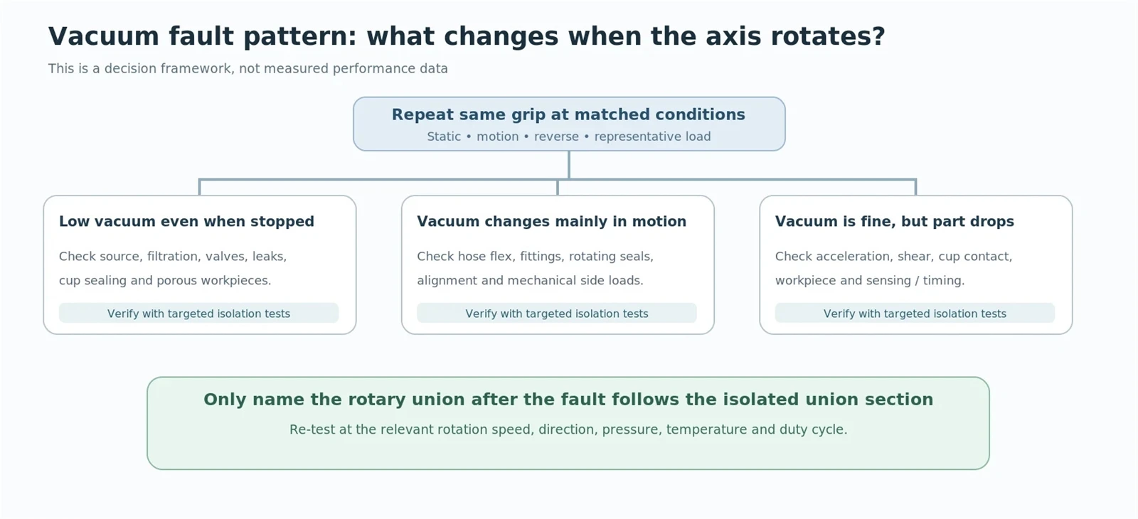
| Weak vacuum when stopped and during rotation | Low source capacity, supply restriction, faulty valve, permanent hose or cup leak | Reference test at P1; then isolate stationary line and tool branches. |
| Vacuum falls only at particular shaft angles | Hose tension, local bend, fitting movement, position-dependent union or tool sealing issue | Log pressure versus angle in both directions; immobilize or support external hose motion where permitted. |
| Pressure holds while stationary but rises during motion | Dynamic seal behavior, unsupported hoses, radial load, runout, tool vibration | Repeat with the downstream tool circuit isolated by an approved procedure; compare under matched motion. |
| Vacuum at source is acceptable but tool responds slowly | Undersized tubing, restrictive ports, valve response, excess volume or blocked filter | Compare time-to-threshold and P2/P3/P4 under flowing pick conditions. |
| Part drops during acceleration although vacuum indication remains normal | Insufficient holding margin, shear load, cup peel, friction or workpiece deformation | Evaluate actual part mass, orientation, acceleration and cup contact instead of only pressure. |
| Failures follow material batches | Porosity, roughness, packaging folds, moisture or surface contamination | Compare production parts with a consistent reference surface at identical settings. |
| Fault occurs only during pickup or release | Vacuum confirmation threshold, sensor placement, switching sequence or blow-off control | Capture valve commands, sensor state and pressure rise/fall against the motion profile. |
Reference documentation from SMC lists workpiece leakage, ejector supply pressure, cup deterioration and blocked filters among vacuum-gripping fault causes. These variables should be checked before attributing every failure to the rotating passage.
Distinguish Pressure Loss, Actual Air Ingress and a Holding-Force Problem
A pressure difference is not automatically a leak
Under flowing conditions, a narrower union passage, hose or fitting may create a pressure difference. That loss of pressure available at the gripper can make pickup slow even when the system seals are intact. Compare pressure while flowing at a stated rate, and separately evaluate leakage using an appropriate approved method. Do not treat a blocked-line pressure test and a production-flow test as equivalent.
A vacuum-rise test needs a defined volume and duration
If an isolated vacuum volume is sealed and its absolute pressure rises toward atmospheric, gas is entering or being released within that volume. The trace alone does not tell whether the cause is an external leak, trapped gas, desorption, thermal drift or unsuitable instrumentation. Report the isolated volume, starting absolute pressure, temperature, duration, sensor resolution and acceptance rule. If the equipment requires a quantitative leak rate, use a validated procedure or instrument designed for that purpose.
Grip force is a separate acceptance condition
For an idealized flat sealed contact, normal-direction holding force scales with the effective pressure difference and effective contact area. Real cups may lose area, friction or seal integrity when pulled sideways, peeled, accelerated or used on porous materials. A stable manifold gauge does not prove adequate retention during motion. Select the cup layout and safety factors based on the supplier's method and the machine risk assessment. Festo's vacuum technology guide discusses the effect of surface leakage on gripping performance; Piab's suction-cup guidance distinguishes leakage at the cup lip from material permeability.
Run a Dynamic Test Matrix With Defined Pass/Fail Criteria
A successful stationary bench check is only a baseline. The machine should be validated at the operating point where the fault was observed and the other representative conditions in its actual duty cycle. Assign acceptance limits from the workpiece, cycle time, holding force and system safety requirements; none of the values below are ByTune factory specifications.
| Test condition | Record | Decision supported |
|---|---|---|
| Stopped with reference test surface | P1–P4 as available; build-up time; isolated rise test | Baseline source, piping and basic sealing. |
| Constant nominal rotation, no part | Vacuum pressure, angle, flow/source duty, hose behavior | Rotation-related interface or tube behavior without cup loading. |
| Indexing, starts/stops and reversals | Transient vacuum minima, response delays and sensor state | Motion-dependent sealing, hose and control effects. |
| Representative workpiece at normal throughput | Pick threshold time, retained part, false-positive grip signal, drop events | Real gripping function. |
| Worst defined normal part and motion | Vacuum behavior, acceleration, orientation and grip margin | Production acceptance within the approved machine operating envelope. |
| After relevant endurance exposure | Repeat vacuum-rise, flow and gripping tests; inspect approved accessible parts | Whether leakage or function changed over the test interval. |
For each test, document sensor type, calibration, pressure convention, sampling rate, speed, direction, temperature, workpiece, source condition, allowed deviation and stop criteria. Use synchronized data rather than comparing measurements taken on different production cycles. Where pressure data must cross the rotating axis, use a validated sensor/telemetry path or approved signal interface; never assume unused electrical slip-ring circuits preserve sensor accuracy.
Stop and make the machine safe if the fixture cannot retain the workpiece, an uncontrolled leak threatens the process, hoses foul the rotating assembly, the unit overheats, or a safety-related sensor is unreliable. Testing must not expose operators to dropped loads, pinch points or released compressed air.
When Does the Rotary Union Actually Need Service or Redesign?
The union becomes the leading suspect when the source and tool branches have passed independent checks and a repeatable abnormality remains within the isolated rotating passage under approved test conditions. Evidence is stronger if the problem tracks rotation angle or speed and persists after hose strain and misalignment are corrected. Even then, the component service procedure and supplier inspection should determine the next action.
Do not open a sealed rotary union without authorization, or replace seals with unverified materials. Vacuum compatibility depends on the actual seal design, differential pressure, materials, speed, lubrication or dry-running limits and contamination exposure. A unit intended for positive-pressure compressed air should not automatically be accepted for vacuum service.
When an OEM needs an updated interface, provide the ByTune pneumatic/hybrid product team with evidence from the isolated test and the actual simultaneous operating conditions. For systems using electric power or sensor channels across the same rotation axis, distinguish those circuits from the vacuum passage; the combination specification guide covers the broader design-selection task.
What to Send With a Vacuum-Gripper Fault Report
A concise report helps a maintenance team, machine OEM or rotary-union supplier reproduce the condition without guessing the cause. Include the machine arrangement and the shortest test that reliably triggers the fault.
| Field | Information required |
|---|---|
| Machine and rotation | Stationary/rotating boundary; whether vacuum, compressed air or electrical power crosses it; axis position, speed and reversal. |
| Actual vacuum path | Source type; valve and filter positions; hose sizes and lengths; rotary union; passage count and port arrangement; tool manifold and cups. |
| Failure signature | Pick failures, late confirmation, pressure drift, lost parts; exact operating event and repeat frequency. |
| Measurements | P1–P4 where available; units and pressure convention; timestamps; time to threshold; test volume/temperature when applicable. |
| Isolation results | Which sections passed or failed; test fittings and valve states; stationary-versus-rotating comparisons. |
| Workpiece and motion | Material permeability, cup type, orientation, acceleration, cycle time and representative production variation. |
| Constraints | Allowable vacuum drop, leakage test method, required build-up time, permitted downtime, cleanability and service restrictions. |
A rotary vacuum fault report should end with a testable conclusion: which subsystem is implicated, which alternatives were ruled out, what evidence remains, and what dynamic retest will verify the repair. Changing the rotary union without isolating the fault does not establish that the diagnosis was correct.