

A slip ring can carry strain-gauge measurement circuits from a rotating shaft to stationary instrumentation, but electrical continuity alone does not establish measurement accuracy. The useful design question is whether the entire path-from bridge excitation and sensor wiring to rotating contacts, cables, signal conditioning and the data-acquisition system (DAQ)-preserves the required strain or torque measurement while the shaft turns.
For a rotating test bench, start by deciding where the Wheatstone bridge is completed, where its excitation is regulated and sensed, and whether the raw bridge output or a conditioned signal crosses the rotary interface. Then assign electrical paths, control interference, and validate the assembled measurement chain at the relevant speeds and loads. This guide addresses that measurement problem; it does not claim that any particular ByTune model has a certified strain-measurement accuracy.
Figure 1. Generic rotating strain measurement architecture. A full bridge may need separate excitation and differential signal paths; additional sense or shielding connections depend on the instrumentation.
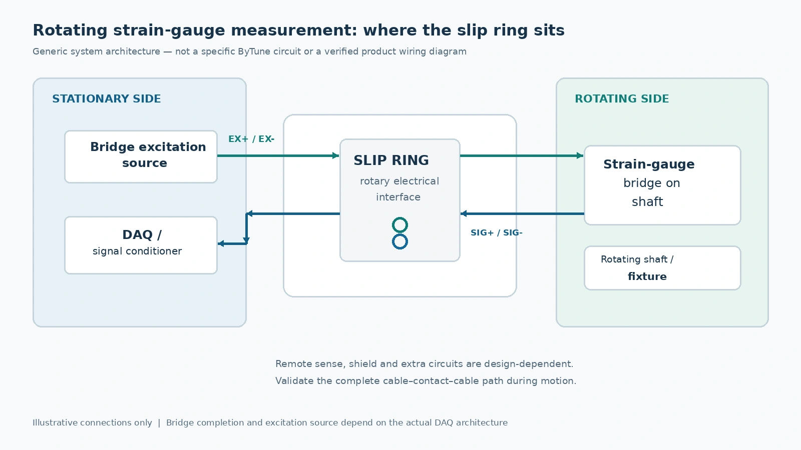
First define the measurement boundary
Consider a strain-gauged shaft in a laboratory drive train. Gauges are bonded to the rotating member and connected as the chosen bridge configuration. An end-of-shaft or through-bore slip ring provides conductive paths to the stationary instrumentation. Alternatively, electronics on the shaft may amplify or digitize the signal before transmission. These architectures have different sensitivity to contact variation and electromagnetic interference.
Record both the mechanical boundary and the electrical one before selecting the hardware. The rotating side includes the gauges, adhesive and protection, bridge completion (if mounted there), lead wires, any preamplifier, and the slip-ring rotor. The stationary side may include excitation, bridge conditioning, acquisition, shaft-angle measurement and analysis software. Shaft grounding, cable screens, housing bonds and power circuits must also be mapped, rather than assumed to be interchangeable return paths.
| Interface element | Question to resolve | Design consequence |
|---|---|---|
| Measurement | Torque, bending, axial strain or a combination? | Determines gauge orientation, bridge configuration and cross-sensitivity assessment. |
| Bridge location | Complete the bridge on the rotating shaft or in stationary instrumentation? | Changes conductor count and exposure of sensitive leads to rotary-contact variation. |
| Signal at the interface | Raw millivolt-level bridge signal, amplified analog output or digital data? | Changes noise budget, channel design, power needs and acceptance measurements. |
| Excitation | Where is it supplied and where is its actual voltage measured? | Determines the sensitivity to excitation lead and contact resistance. |
| Motion | Continuous rotation, reversal, acceleration, maximum speed and running hours? | Controls mechanical selection and the dynamic test sequence. |
| Installation | Is a shaft end free, or is a clear bore required? | Guides the end-of-shaft versus through-hole integration review. |
ByTune's research and laboratory slip ring applications page covers the wider laboratory-equipment context. The task here is narrower: keeping the rotating strain measurement trustworthy, rather than choosing a generic slip ring for every laboratory service.
Bridge wiring determines how many paths must cross the slip ring
A strain gauge produces a small resistance change. A Wheatstone bridge converts the resistance changes into a differential voltage related to applied strain and bridge excitation. Quarter-, half- and full-bridge arrangements are not interchangeable: the valid choice depends on whether the objective is torsion, bending, axial strain, temperature compensation or a combination. Gauge placement and bridge completion belong to the measurement design, not to the slip-ring vendor.
NI's strain-measurement guidance explains bridge completion, excitation, remote sensing, filtering and calibration. HBK's Wheatstone bridge technical guide explains how bridge arrangement changes sensitivity and how unwanted mechanical influences can be reduced. Those references are useful for selecting the bridge before allocating rotary circuits.
Completed full bridge on the shaft
For a completed, passive full bridge with stationary excitation and differential measurement, a common starting point is four independent conductor paths: EX+, EX−, SIG+ and SIG−. Four is a wiring example, not a universal slip-ring specification. Remote-sense leads, shields, a separate protective bond, other sensors, a temperature channel or a rotating amplifier can change the circuit schedule. Whether a given shield consumes an isolated slip-ring path depends on the complete grounding architecture.
Quarter or half bridge with completion elsewhere
For a quarter bridge, the gauge may be only one arm of a bridge completed in the measurement instrument. In that case, lead-wire resistance and changes in its temperature can enter the measurement more directly. Three-wire quarter-bridge compensation depends on wiring symmetry and the acquisition module's intended connection scheme. Never substitute a four-channel full-bridge diagram for a three-wire quarter-bridge installation without checking the instrument manual. The same caution applies to half-bridge completion and any optional compensation conductors.
A practical channel allocation example
| Path or function | Basic passive full-bridge example | What needs verification |
|---|---|---|
| EX+ and EX− | Two excitation paths | Actual excitation at bridge, allowable drop, contact/load current, supply stability |
| SIG+ and SIG− | Two differential measurement paths | Input impedance, common-mode range, interference, bandwidth, cable symmetry |
| SENSE+ and SENSE− | Optional additional paths | Whether the DAQ supports remote sensing and where sense points physically terminate |
| Shield and chassis | As the grounding design requires | Shield termination, protective bonding, unwanted return loops and isolation |
| Other circuits | Separately scheduled | Angle encoder, rotating electronics power, temperature or additional bridges |
Count conductors after choosing the measurement scheme. A design described merely as "four signal wires" does not specify the excitation source, allowable noise or whether the circuit is suitable for the rotating experiment.
Why motion can change a strain-gauge reading
Strain channels can be sensitive to errors that appear small on an ordinary power circuit. The mechanism matters: not every unwanted fluctuation is contact noise, and not every resistance change produces the same output error.
| Potential mechanism | How it may appear | Diagnostic distinction |
|---|---|---|
| Excitation-path resistance variation | Bridge excitation changes, giving apparent gain or offset changes depending on the circuit | Measure voltage at the bridge where accessible; compare with supply-side voltage versus shaft angle. |
| Measurement-path disturbance | Steps, spikes or excess noise on a low-level differential signal | Check input impedance, contact stability, amplifier common-mode range and both signal legs. |
| Motor-drive EMI | Features synchronized to PWM, switching or drive-current transitions | Repeat with adjacent power electronics disabled or operated separately under controlled conditions. |
| Shield or reference error | Common-mode pickup, noise change after cable movement or grounding changes | Trace shield termination and return currents across the complete assembly. |
| Mechanical strain unrelated to target load | Speed-dependent drift or periodic signal correlated with shaft angle | Separate true bending, runout, centrifugal or fixture loading from electrical artifacts. |
| Thermal and lead-wire effects | Slow drift after warm-up or changing speed | Record bridge temperature, excitation, lead routing and thermal stabilization. |
These mechanisms should be investigated separately. For the behavior of the sliding electrical contact itself, see ByTune's static and dynamic contact-resistance guide. For general sensor-channel EMI and grounding diagnostics, the electrical noise troubleshooting guide serves a broader function than this strain-measurement procedure.
Remote sensing and amplification solve different problems
Remote sensing addresses excitation loss
If the selected strain-measurement instrument supports remote sensing, dedicated sense conductors can measure excitation nearer the bridge and allow the excitation system to compensate for series voltage drop. This can reduce gain error created by lead-wire and rotary-contact resistance in the excitation path. It does not guarantee that a varying measurement-signal contact, electrical interference or mechanical strain artifact disappears.
Sense-lead routing, controller stability, the permissible lead resistance and the exact DAQ mode must be validated as a system. Some measurement modules use shunt calibration rather than remote sense for a particular quarter-bridge configuration. For example, NI's instrument-specific remote-sense and shunt-calibration documentation distinguishes these functions. A correction method for one DAQ mode should not be generalized to every bridge or instrument.
Moving the amplifier to the rotating side changes the signal boundary
When a raw bridge output is exceptionally small relative to the expected interference, signal conditioning near the gauge may be worth evaluating. An amplifier on the rotating shaft can reduce the length of an unamplified sensor lead and send a higher-level analog output-or, with suitable active electronics, digital data-across the rotary interface. However, the design now needs a qualified rotating-side power supply, thermal and vibration assessment, sufficient bandwidth, calibration stability and a defined transmission protocol where applicable.
Locating electronics on the rotating side is an architectural choice, not an automatic requirement. It may improve the noise margin while increasing balancing, space, power and maintainability constraints. Compare performance on the same shaft and with the same DAQ bandwidth before selecting the more complex solution.
Plan calibration around the complete rotating measurement chain
A strain measurement can be well calibrated while stationary and still drift during rotation. Calibration and validation are complementary: calibration establishes the conversion between electrical output and the chosen measurand under defined conditions; dynamic testing checks whether that conversion remains valid in the installed system.
- Fix the configuration. Record gauge pattern, bridge completion, excitation setting, slip-ring circuit map, cable lengths, shielding, amplifier gain, filters, DAQ range, sampling rate and shaft mounting. Any change may invalidate the comparison.
- Record a stationary zero and reference. With the shaft stopped at documented conditions, capture bridge excitation, raw or conditioned output, temperature and an approved unloaded or reference-load state.
- Apply the appropriate calibration method. Use an application-approved physical load calibration where practicable. Bridge offset nulling and shunt calibration are useful checks, but a shunt performed at the wrong location may not exercise the same series contacts as a physical strain signal.
- Repeat in controlled rotation. Test low speed, nominal speed, maximum required speed, reversals where applicable, and relevant warm-up states. Measure reference load and output simultaneously when the test bench permits.
- Separate error sources. Use a reference sensor or controlled comparison, record shaft angle and speed, and compare motor-drive-on versus drive-off conditions where safe. Do not immediately attribute a periodic artifact to the slip ring.
- Document the acceptance decision. Compare observed zero drift, gain change, noise, outliers and recoverability with limits derived from the experiment's uncertainty budget-not a generic contact-resistance number.
For a rotational torque experiment, the physical loading method, fixture dynamics and gauge arrangement determine the traceability and limits of the calibration. Shunt calibration cannot, by itself, establish traceability of the complete torque-measurement chain to a mechanical reference.
A dynamic test matrix for the measurement interface
Before ordering or approving a rotary interface, specify measurable limits for the complete strain-measurement chain. The values will depend on bridge sensitivity, the required uncertainty, the acquisition bandwidth, operating speed and what the rotating shaft actually experiences.
| Test state | Record together | Pass/fail basis |
|---|---|---|
| Stationary, unloaded | Zero reading, excitation at source and bridge if accessible, temperature, bandwidth | Approved baseline and zero stability |
| Stationary, calibrated load | Applied reference load, indicated strain/torque, gain and repeatability | Project measurement error and repeatability limits |
| Constant-speed unloaded rotation | Speed, shaft angle, zero shift, RMS noise and peak transient count | Motion-induced offset/noise budget |
| Constant-speed loaded rotation | Reference load, measured output, excitation, error versus speed | Dynamic span or gain error limit |
| Acceleration and reversal | Transient magnitude, settling time, angle and control state | Experiment-specific transient rejection or recovery requirement |
| Drive switching comparison | Sensor trace, drive current or PWM state, other channels active | Interference contribution below approved threshold |
| Hot condition/endurance | Drift, noise, temperature, contact behavior and calibration check | Required stability over intended duty and environmental range |
The DAQ sampling rate and analog bandwidth must be high enough to reveal errors that matter to the intended measurement. A slowly averaged display can conceal short interruptions, while an unnecessarily wide bandwidth can increase observed noise without improving useful information. Record both filtering and bandwidth for comparisons.
A useful separation test compares the same instrumented shaft with the interface stationary, rotating under no applied torque, and rotating under a known applied torque. If an angle-locked feature appears only with rotation, inspect mechanical effects and contact behavior together; correlation is a diagnostic clue, not proof of cause. HBK also notes that rotational effects can influence a torque sensor's output in ways that depend on the application and speed; see How to Select a Rotating Torque Sensor.
When a slip ring is not the best measurement architecture
Conductive slip rings remain useful where engineers need simple continuous connections to a rotating bridge, an accessible DAQ and a mechanical installation that can be maintained. But there are cases where the measurement chain is better served by a rotating amplifier with a higher-level output, a rotating digitizer, or a non-contact telemetry system.
| Architecture | Consider when | Confirm before deciding |
|---|---|---|
| Passive bridge through conductive slip ring | Low channel count, qualified contact stability, accessible end of shaft or through-bore geometry | Bridge layout, excitation error, dynamic noise, contacts and strain measurement accuracy |
| Rotating amplifier plus conductive interface | Raw millivolt signal cannot meet the noise budget across the available wiring path | Rotating power, packaging, amplifier drift/bandwidth, signal or data path qualification |
| Non-contact telemetry | Contactless transmission or a mechanically inaccessible shaft is a key constraint | Powering, synchronization, mounting, bandwidth, latency and environmental suitability |
Different architectures may be justified for different experiments. The comparison should be based on an approved uncertainty budget and the actual operating profile rather than a broad claim that one technology is always more accurate.
What to send for a strain-measurement rotary-interface review
When a slip ring remains a viable option, the supplier needs more than the phrase "strain gauge signal." The following short specification helps prevent the wrong contact layout, circuit count or testing scope from being proposed.
| Requirement group | Information to provide |
|---|---|
| Measurement | Strain/torque/bending objective, sensor count, gauge factor and bridge configuration |
| Signal and excitation | Bridge resistance, excitation voltage, expected mV/V output, bandwidth, allowable measurement error |
| Wiring | EX+/EX−, SIG+/SIG−, optional SENSE leads, other circuits, shield and grounding layout |
| DAQ | Model and measurement mode, signal conditioner, sample rate, filtering, remote sense and calibration method |
| Rotation | Normal/maximum RPM, continuous or reversing motion, acceleration and expected duty |
| Mechanical | Free shaft-end availability, shaft diameter, required bore, allowable OD/length, rotor-stator mounting, cable exits |
| Other loads | Adjacent motors and drive electronics, concurrent current and high-speed channels |
| Environment | Temperature, vibration, contamination, oil/moisture, maintenance access and lifecycle requirement |
| Acceptance | Approved uncertainty/noise/zero-drift budget, reference load procedure, rotating test conditions and test records |
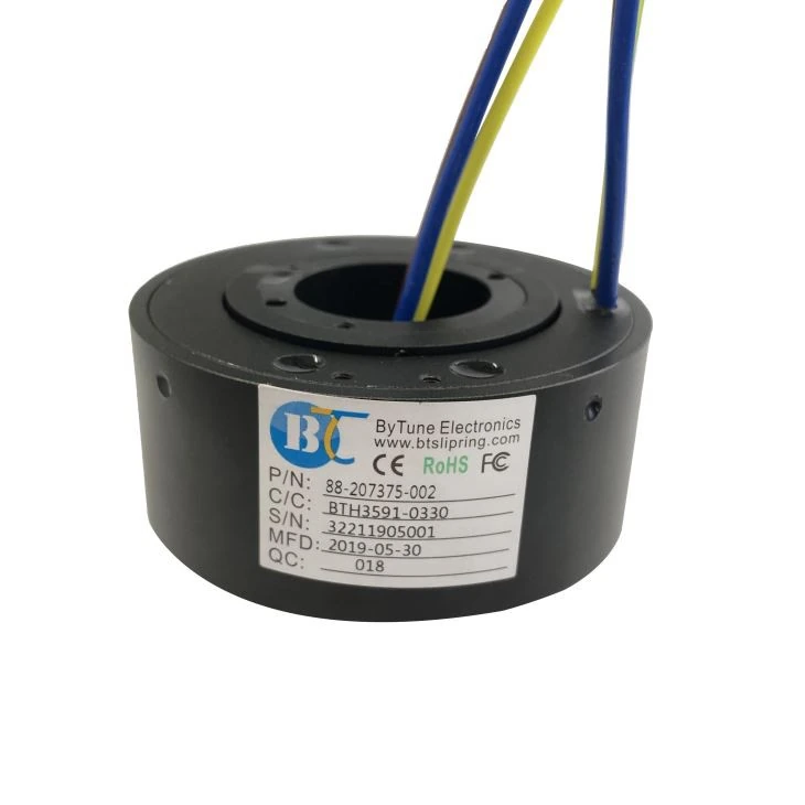
Figure 2. Real ByTune through-hole product visual. It illustrates a mechanical center-bore option only; this photograph does not establish strain-gauge compatibility, measurement accuracy or a product-specific test result.
The ByTune through-hole product family is a relevant mechanical reference if the assembly needs to surround an existing shaft. If electrical contact layout or the channel combination needs engineering review, use the custom slip ring design route with the complete circuit schedule and acceptance criteria.
The decision rule is straightforward: choose the rotary-interface architecture only after the bridge, wiring, error budget and dynamic test have been defined. A contact-count or nominal RPM match is necessary for integration, but not sufficient evidence of measurement quality.