

A resistance temperature detector (RTD) can be mounted on a rotating drum, heated platen, test spindle or instrument carousel while the temperature controller remains stationary. A slip ring makes the electrical connection possible. It does not, by itself, establish the accuracy of the temperature measurement. The critical question is how excitation current, voltage-sensing leads, contact resistance and electrical interference behave across the complete rotating interface.
For a two-wire RTD, the slip-ring contacts become part of the resistance being measured. A three-wire circuit can compensate much of the lead resistance, but its result depends on the measurement circuit and the match between lead paths. A four-wire, or Kelvin, circuit separates excitation from voltage sensing and is usually the strongest starting point when the error budget is tight. None of these arrangements makes an open contact, incorrect wiring or interference disappear.
This guide is for engineers specifying a rotating RTD measurement chain. It covers conductor allocation, the error mechanisms unique to a moving contact, and a repeatable validation procedure. It is not a guarantee that any untested slip-ring model supports a particular RTD sensor, temperature accuracy or operating speed.
First Locate the Stationary-to-Rotating Boundary
Before counting conductors, draw the full measurement chain: stationary RTD input or data acquisition module, its excitation and measurement terminals, the fixed-side harness, the slip ring, the rotating-side harness and the RTD element. Identify any heater, motor drive or solenoid sharing the same rotary assembly. Those additional loads matter because their switching currents may disturb a low-level resistance measurement.
Confirm that the RTD actually crosses the rotary boundary. Some machines keep the temperature probe and transmitter stationary even when the monitored surface rotates. In that arrangement an RTD slip-ring channel may not be needed. Conversely, if the sensor is on the rotor but an approved transmitter is mounted beside it, the raw RTD leads can remain local; the electrical services crossing the slip ring are then the transmitter's supply and output, not necessarily the RTD's own leads.
| Architecture | What crosses the slip ring? | What must be verified? |
|---|---|---|
| Direct two-wire RTD | Two RTD leads | Combined lead/contact resistance and its change during rotation |
| Direct three-wire RTD | Three independent RTD leads | Instrument compensation method and unequal, time-varying path resistance |
| Direct four-wire RTD | Two excitation and two separate voltage-sense leads | True Kelvin termination, continuity, interference and rotating measurement stability |
| Conditioning on the rotor | Defined transmitter power, return and output/data paths | Transmitter compatibility, reference and signal performance at the boundary |
These are wiring architectures, not ByTune model specifications. Each independent sensor conductor needs an appropriately assigned electrical path unless the actual measurement design provides an approved alternative. Never borrow a protective-earth conductor or an unverified chassis path as a substitute for a sensor lead.
Choose the RTD Wiring Topology Before Counting Slip-Ring Channels
An RTD is a temperature-dependent resistor. Measurement electronics pass an excitation current through the element and infer resistance from the resulting voltage. NI's RTD connection guide and Texas Instruments' RTD measurement application note explain why the choice of wiring method affects lead-resistance error.
| RTD connection | Minimum independent sensor paths across boundary | Main advantage | Primary limitation in a rotating assembly |
|---|---|---|---|
| 2-wire | 2 | Simple channel allocation | Excitation leads and contact resistance are included in measured resistance |
| 3-wire | 3 | Can correct lead resistance with a supported RTD input | Unequal or changing lead/contact resistance limits the correction |
| 4-wire (Kelvin) | 4 | Separates current drive from high-impedance voltage sensing | Does not by itself suppress opens, coupled noise or wrong sensor topology |
The table lists the minimum raw sensor conductors, not a complete machine-level ring count. Shields, chassis bonds, spare channels, sensor housings, power paths and other services require a separate allocation decision. Some RTD input modules implement three-wire compensation differently, so the module's wiring diagram-not generic wire color or a familiar terminal name-remains authoritative.
Two-Wire RTD: Series Resistance Appears as Temperature Error
With two-wire measurement, the instrument cannot distinguish the RTD element from resistance in its two leads and electrical contacts. In simplified form, the resistance seen by the instrument is the sensor resistance plus the series resistance of both complete lead paths, including the two slip-ring channels and connectors. If those series resistances change with shaft angle, their contribution changes too.
Consider an illustrative Pt100 measurement near 0°C. A platinum RTD with a nominal sensitivity near 0.385 ohm per degree Celsius would show approximately 0.4 ohm of extra indicated resistance if each of the two complete external paths contributed 0.2 ohm. In this simplified local calculation, the corresponding apparent temperature offset is roughly 1°C. Those figures are an engineering example only, not a measured property or rating of a ByTune slip ring. Actual error depends on the RTD curve, measurement method, leads, contacts, temperature and operating conditions.
A one-point calibration can remove a stable offset. It cannot prove that the same offset remains stable when the rotor turns, the harness warms up, or a contact briefly becomes resistive. A two-wire arrangement can still be reasonable for a less demanding measurement, especially with a higher-resistance element and a demonstrated error budget; it should not be described as categorically unusable. The correct decision is based on the complete installed error, not wire count alone.
Three-Wire RTD: The Compensation Method Determines the Error
A three-wire RTD uses an additional conductor so compatible instrumentation can estimate and compensate lead-resistance effects. The exact method may use matched excitation currents, multiple ADC measurements or a bridge arrangement. Many designs depend on sufficiently equal lead resistances; Analog Devices' precision RTD discussion explains that the resistance-matching assumption matters in practice.
At a slip ring, the three routes may not remain equally resistive as the machine moves. Separate sliding contacts can experience different instantaneous conditions. Consequently, even a well-balanced three-wire cable does not automatically imply three balanced rotating paths. The instrument may compensate a common or matched lead contribution while residual mismatch appears as temperature error.
For a three-wire specification, ask the engineer responsible for the RTD input to identify the actual compensation topology. Record which leads carry excitation, which is used for sensing and how the measurement responds if one contact path changes while the other two remain steady. Use a validated RTD input rather than simply adding a third ring to a two-wire ohmmeter. A three-wire configuration is an engineering trade-off between channel count and measurement uncertainty, not a blanket guarantee of accuracy.
Four-Wire Kelvin Sensing: Reject Static Resistance, Not Dropouts
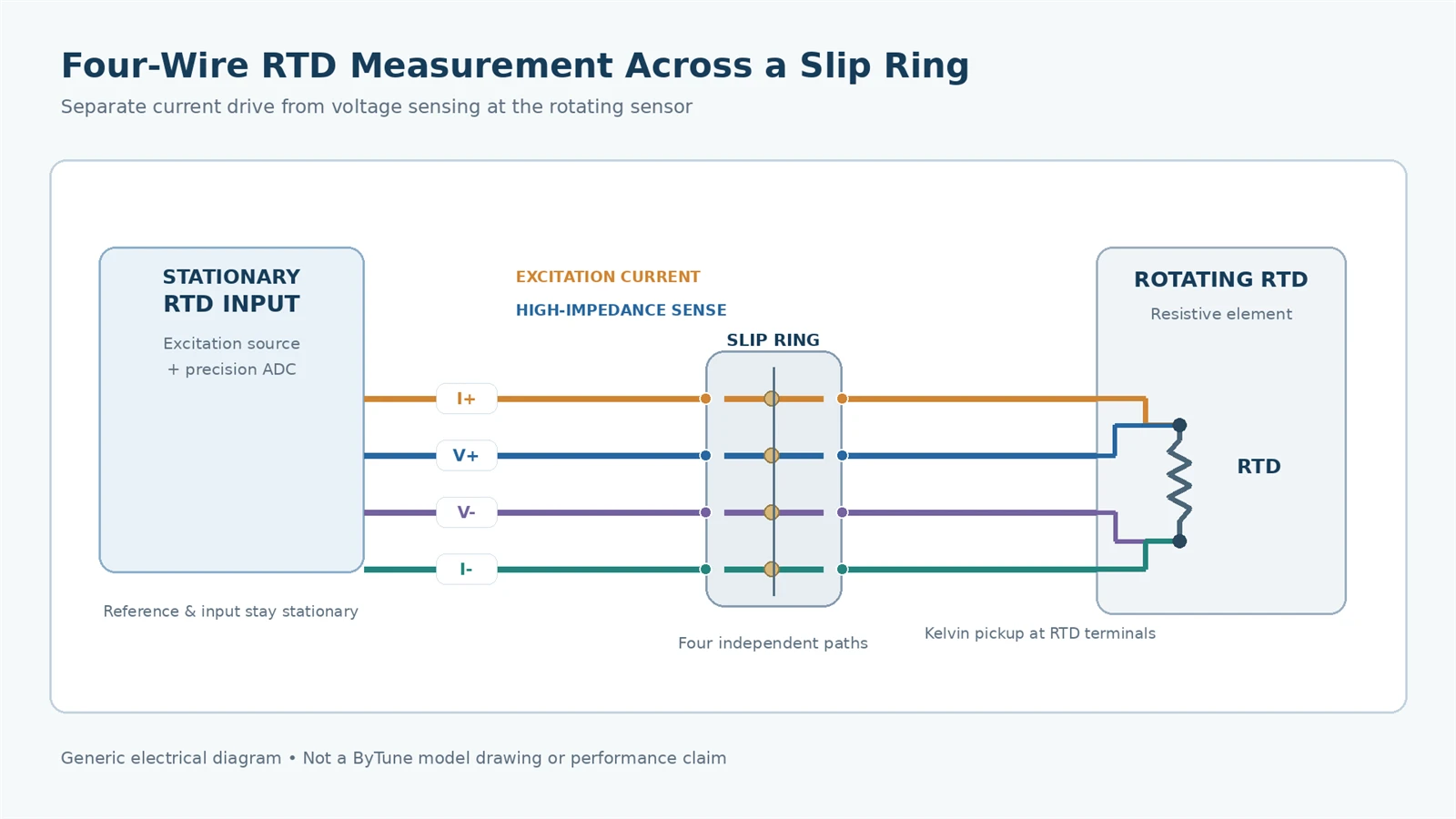
In a true four-wire arrangement, one pair carries current to and from the RTD element and a second pair senses the voltage at the RTD terminals. The sensing input is high impedance, so very little current normally flows in its leads. Voltage drops in the excitation leads therefore do not appear as part of the sensed RTD voltage in the same way they do in a two-wire circuit. NI, TI and Analog Devices describe this principle in their RTD documentation.
When the RTD is on the rotating side and the measurement module is stationary, all four paths must remain correctly identified across the interface: excitation positive, sense positive, sense negative and excitation negative. The sense conductors should meet the sensor terminals at the intended Kelvin pickup points; joining the sense leads to the excitation leads on the stationary side defeats much of the purpose of the four-wire arrangement.
Four-wire measurement reduces the systematic influence of contact and lead resistance in a properly functioning high-impedance sense path. It does not guarantee a correct reading during intermittent opens, excessive common-mode interference, instrument overload, leakage, incorrect filtering or rapid contact disturbances. A high-impedance sense lead that opens briefly may cause a fault, a spike or a held value, depending on the measurement instrument. An excitation-path interruption can prevent a valid measurement altogether. Those are system behavior questions that must be tested, not inferred from the word Kelvin.
One further limit is the excitation source. When contact-path resistance rises, the RTD interface must still have sufficient excitation-current-source voltage headroom and input common-mode range for the whole circuit. The Kelvin voltage pair cannot repair a current source that has left regulation. The RTD input-module datasheet and the installed maximum path resistance, not the four-wire label, decide whether that condition is satisfied.
Build a Channel Map That Can Be Audited
Prepare the pin-to-pin map before choosing a slip-ring package. Label every channel at both sides of the rotating boundary and compare it with the RTD module manual. An example four-wire map is shown below.
| Stationary instrument terminal | Rotary path | Rotating sensor connection | Inspection or test |
|---|---|---|---|
| I+ / EXC+ | Channel A | First RTD terminal: excitation | Confirm current-source path and continuity |
| V+ / SENSE+ | Channel B | First RTD terminal: voltage sense | Confirm separate route to the Kelvin pickup |
| V− / SENSE− | Channel C | Second RTD terminal: voltage sense | Confirm polarity and input reference |
| I− / EXC− | Channel D | Second RTD terminal: current return | Confirm current return path and continuity |
Channel letters A–D in this table are placeholders, not part numbers, actual product pin numbers or a claim that any particular ByTune slip ring provides those channels. Follow the instrumentation manufacturer's terminal convention; I+/I− and V+/V− are useful functional descriptions but not universal labels. For a three-wire system, produce its own map rather than removing one arbitrary row.
Build the Measurement Error Budget Before Selecting Channels
There are two separate acceptance questions: how accurately the instrument measures temperature in the first place, and what additional error is introduced by the installed rotary interface. The second cannot be assessed from a contact-resistance number without considering the selected RTD wiring method and input electronics. Record the two limits separately, then test the finished chain against the system requirement.
- Sensor and process: RTD element tolerance, sensor mounting, heat transfer, thermal gradients and calibration uncertainty. Keep actual process-temperature changes separate from electrical measurement error.
- Excitation and conversion: current-source accuracy and compliance, ADC gain/offset, reference strategy, input common-mode range, wiring mode and linearization. Check the actual module documentation.
- Rotary conductors: lead and connection resistance, each slip-ring contact's change with position/temperature, and three-wire path mismatch where the measurement depends on matched leads.
- Excitation self-heating: the RTD dissipates approximately P = I²R under current excitation. The resulting temperature rise depends on the sensor's thermal environment and must be considered separately from contact-resistance error; lowering current also changes the available signal level.
- Dynamic effects: contact interruptions, coupled interference, sample filtering, fault handling, vibration and warm-up drift. These require a time-correlated test; a single static meter reading is not enough.
The two-wire example above illustrates why the total path resistance must be part of the uncertainty budget. A three-wire error calculation must instead use the input module's actual compensation algorithm; a four-wire calculation must also check excitation-source headroom, input conditions and dropout behavior. Use the instrument's configured RTD characteristic over the full temperature range rather than extending a local slope approximation. See the Analog Devices RTD design guide for lead resistance, signal conditioning and calibration considerations.
Keep Sensor Wiring Separate From Shielding and Safety Bonding
A clean signal depends on the whole cable system. Record the twisted-pair or cable construction, shield coverage, shield termination, chassis bonds and the normal route for sensor excitation current. Plan where the stationary and rotating structures are referenced. The most appropriate shield treatment depends on the installed electronics, cable geometry and EMC design; blindly grounding both ends or leaving all shields floating is not a universal solution.
In mixed heater-and-sensor assemblies, list the heater's normal current and switching method separately. Do not route RTD sense conductors as if they were heater returns, and do not assume a slip-ring shield track is equivalent to an approved protective-earth connection. The ByTune power-and-data overview covers broader power/signal separation considerations; this RTD guide is concerned specifically with the resulting temperature measurement.
Excitation current and input filtering also matter. Excessive current can cause sensor self-heating, while protective filters or leakage paths can introduce measurement error in a precision front end. The measurement module documentation should determine current, filtering, input protection and permissible common-mode voltage. Additional rings do not replace those electrical design checks.
When to Condition the Sensor Signal on the Rotating Side
If long rotating harnesses, low-level measurement noise or limited slip-ring channel availability make direct RTD wiring difficult, one alternative is to put a compatible RTD transmitter on the rotating assembly. That keeps the raw RTD wiring close to the sensor. The slip ring then carries the transmitter's required power and output or communications interface. Depending on the transmitter, this may be an analog current loop, voltage output or digital link; each has its own grounding and validation requirements.
This architecture is not automatically superior. It adds electronics that must survive rotor temperature, vibration, centrifugal loading, power variation and installation constraints. The transmitter must be compatible with the actual RTD type and 2-/3-/4-wire configuration. Signal format and supply budget should be verified against the complete rotating interface. Do not assume that a transmitter, any standard signal ring or an unspecified ByTune model is already qualified for this design.
Dynamic Validation: Test the Temperature Measurement, Not Just Continuity
The acceptance method should compare the installed rotating measurement with a suitable reference. Ideally, use a known stable temperature condition or a traceable resistance/RTD simulator appropriate to the chosen input. Ensure the simulator and instrument arrangement can safely reproduce the intended sensing circuit; a generic resistor or voltage source is not a substitute for all RTD module functions. Record the reference uncertainty, the module filtering and the sampling rate before testing.
Reference validity: A fixed precision resistor or RTD simulator can test the instrument and rotary electrical paths with a known stable equivalent resistance, provided the actual instrument supports the chosen connection and excitation method. If the resistor or simulator is installed on the rotor, its secure mounting, operating environment and the way its value is verified must be controlled. For real temperature testing, use an independent, appropriately calibrated reference measuring substantially the same thermal location; avoid calling the same slip-ring channel under test its own independent reference. A rotor-side logger can help if its time base and accuracy are established and its installation is mechanically safe.
Begin with the same sensor and instrument connected through a stationary harness, if possible. Then add the slip ring and repeat without rotation. Only after those baselines agree should the assembly be driven through its real speed, direction, load and heater-switching conditions. This sequence helps distinguish a calibration or input-module error from an effect introduced by the rotary path.
| Test state | Rotation | Nearby electrical loads | Primary question | Evidence to retain |
|---|---|---|---|---|
| 1. Direct reference | Stopped / no slip ring in path, where practical | Normal quiet state | Can the sensor and input module meet the baseline requirement? | Reference reading, measured error, noise, scaling |
| 2. Slip ring inserted | Stopped | Normal quiet state | Does the added path create a stable offset or wiring fault? | Offset relative to baseline, continuity/pin map |
| 3. Slow rotation | Slow, both permitted directions | Normal quiet state | Are excursions associated with angular position or harness movement? | Time-stamped reading and angle markers |
| 4. Normal operation | Representative speed and duty | Normal process loads | Does accuracy remain inside the real application budget? | Peak and sustained error, excursions, missing samples |
| 5. Electrical aggressors active | Same profile as state 4 | Heater/PWM/drive switching as specified | Does the disturbance follow switching, rotation or both? | Correlated trigger log and sensor waveform |
| 6. Thermal steady state | Representative operation after warm-up | Worst relevant sustained load | Do contact, cable and electronics temperature alter the result? | Ambient, enclosure temperature, measurement drift |
Define the numerical acceptance limits from the OEM's measurement requirement: allowed temperature error, transient excursion amplitude and duration, settling time, permitted missing samples, and any alarm behavior. No universal slip-ring noise value can replace a project-specific temperature budget. A short stable run is not evidence of lifetime reliability; if a life or endurance claim is needed, specify its separate test conditions.
Keep a repeatable test record: wiring revision, sensor and DAQ identifiers, excitation and filtering settings, reference uncertainty, rotary speed/direction, angle or time markers, heater/drive switching state, warm-up condition and raw fault flags. State temperature error with the ring inserted and incremental error relative to the reference setup separately. If a reading changes while the real target temperature also changes, repeat under a controlled thermal condition before attributing the shift to the contact path.
Sampling, Filtering and Fault-Latch Behavior During Rotation
Some RTD modules average over many measurement cycles or use line-frequency rejection. That is useful for noise reduction, but it can also hide short contact disturbances in a displayed value. A controller may show a smooth trend while a higher-rate diagnostic channel captures brief dropouts or saturations. Conversely, changing filter settings during a comparison can make a healthy channel appear worse than it is.
For acceptance, record the RTD module's conversion period, input filter, software averaging, fault-detection behavior, logging interval and the time base used to correlate rotational position. Review raw or least-filtered readings permitted by the instrument, while preserving the production control configuration for the final operational test. A valid comparison needs identical or explicitly documented acquisition settings.
Fault Diagnosis: Separate RTD Errors From Slip-Ring Errors
A temperature reading that changes when a shaft turns does not prove a defective slip ring. Connector strain, rotor cabling, RTD mounting, EMI and measurement settings can produce similar symptoms. Use repeatable signatures to choose the next isolation test rather than replacing components immediately.
| Observed behavior | Possible causes | Next controlled check |
|---|---|---|
| Stable offset immediately after inserting the rotary path | Two-wire path resistance; wrong three-wire configuration; terminal mismatch | Compare direct/through-ring readings, verify channel map and wiring mode |
| Error repeats at the same shaft angle | Angle-dependent contact behavior, harness movement or connector loading | Log reading against angle with nearby switching loads held constant |
| Noise begins only when a heater or drive switches | Coupled EMI, shared return, shield or reference path problem | Switch aggressor on/off while rotation and sample settings stay fixed |
| Three-wire reading drifts more than a four-wire reference | Unbalanced lead/contact resistance or different compensation behavior | Measure individual paths and compare with module's compensation scheme |
| Open-sensor alarm or sudden extreme value | Intermittent excitation/sense connection, harness damage or instrument fault logic | Correlate fault logs with contact/harness tests and sensor-simulator results |
| Value shifts only after warm-up | Changing lead resistance, thermal gradients, sensor mounting or electronics drift | Repeat reference comparison after thermal stabilization |
The ByTune electrical noise diagnosis guide explains the wider distinction between contact noise, interference, crosstalk and grounding. This article's narrower test is whether those disturbances create an unacceptable RTD temperature error in the actual installed measuring chain.
What to Send for an RTD Slip-Ring Engineering Review
An RFQ that says only "four sensor wires" leaves the supplier without the information needed to assess measurement feasibility. Supply a drawing of the stationary and rotating assemblies and a channel list showing each conductor's role. For an accuracy-sensitive temperature system, the useful specification is the allowable error under representative rotation, rather than simply the total number of conductors.
- Sensor: RTD type and nominal resistance, sensing range, element tolerance, 2-/3-/4-wire construction and mounting arrangement.
- Instrument: make and model of RTD input, excitation method, input wiring diagram, filters, conversion interval, and open-sensor diagnostics.
- Rotary boundary: fixed and rotating terminals, circuit map, lead lengths, cable/shield construction and required connector format.
- Power neighbors: heater, motor, solenoid and drive voltages/currents, switching conditions and channel separation requirements.
- Mechanics: shaft or bore envelope, allowable OD/length, mounting, cable exits, speed, reversal, acceleration, duty and permitted service access.
- Environment: actual exposure to temperature, moisture, cleaning, vibration and contamination, without assuming a model-level IP or temperature rating.
- Acceptance: temperature error budget, transient/dropout criteria, required reference method, test duration and operation with neighboring loads active.
If those requirements cannot be satisfied by a verified standard configuration, use the full specification to discuss an appropriately engineered custom slip-ring solution. This is an invitation to evaluate the requirement, not a declaration of tested model compatibility.
Make the Decision From the Measured Error Budget
Choose the RTD wiring topology by the instrument's measurement method and the permitted temperature error, not by spare ring count. A two-wire circuit is simple but includes path resistance in the reading. A three-wire circuit depends on its compensation method and lead matching. Four-wire Kelvin sensing greatly reduces series-resistance error when correctly connected, yet still needs a dynamic test for contact interruptions, EMI and measurement continuity.
Document the rotary boundary, preserve the independent signal paths, verify the installed measurement against a suitable reference, and test while the machine performs its real motion and electrical duty. That is the evidence needed to decide whether an RTD measurement through a slip ring is ready for use.