

Yes, some slip ring designs allow two or more circuits to be connected in parallel for higher load current-but only when the manufacturer approves that exact arrangement and its wiring, terminations, thermal behavior and dynamic performance have been verified. A catalog rating of 10 A per circuit does not, by itself, authorize a field modification that turns two circuits into a guaranteed 20 A path.
The difficulty is not making a connection on the bench. It is keeping each sliding contact, lead, termination and return path within its allowable limits when the assembly is rotating, warming up, reversing and aging. A power channel that carries more than its expected share may overheat even though the total current looks acceptable. This guide explains how to decide whether paralleling is appropriate and what evidence to request before approving it.
First, distinguish parallel power circuits from parallel brush contacts
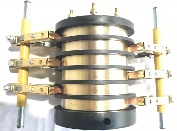
Slip rings contain conductive paths between a stationary side and a rotating side. A product may have several independent insulated rings, each assigned to a separate electrical circuit. It may also use multiple brushes contacting the same ring as part of one manufacturer-designed current path. These are not equivalent configurations.
| Arrangement | What is connected | Engineering implication |
|---|---|---|
| Independent circuits | Separate ring-and-contact paths carrying different loads | Use the documented current rating of each circuit; no additional capability is implied. |
| Customer-wired parallel circuits | Two or more electrically independent ring paths tied together on both stationary and rotating sides | Requires explicit permission, individual branch protection review, current-sharing and thermal validation. |
| Parallel contacts designed into one ring | Multiple brushes or contact points serving the same conductive track | Contact geometry, force and heat flow belong to the manufacturer's design and test, not to a field wiring shortcut. |
| Dedicated higher-current circuit | A contact track, conductor and terminal assembly rated as one higher-current path | Often the clearer option when load sharing cannot be validated or adequate margin is unavailable. |
For example, MOFLON describes parallel 10 A circuits for certain MT100 configurations. That is evidence that a specified manufacturer design can allow this arrangement; it is not evidence that every other slip ring with 10 A channels can be treated the same way. The manufacturer's MT100 product information provides the relevant context: MT100 series configuration notes.
The first decision is therefore not "How many wires can we join?" It is "Does the selected slip ring explicitly permit these identified power paths to be connected in parallel, with the proposed joining points, supply, return and operating duty?" A signal-rated ring, protective bonding path or unverified channel must not be reassigned as additional power capacity by assumption. A manufacturer-designed multi-brush track is not the same as a field modification connecting separately rated circuits.
Map the complete current path, including the return
Start at the source and draw all the way to the load. Mark what remains stationary, what rotates and every physical element crossed by load current. The diagram should show the source terminal, stationary splice or busbar, each supply branch, individual sliding contacts, rotating-side splice, load, return branches, both sets of terminations and protective devices.
A two-channel supply path still needs a suitable return. If the load draws 30 A, dividing the positive feed between two rings does not reduce the 30 A flowing through a single return ring. Do not use a protective-earth or bonding path as the normal load return or as spare load-current capacity. In a three-phase installation, assess each phase and any neutral according to the actual electrical topology; parallel conductors on one phase do not establish the capacity of the rest of the assembly.
| Path element | Question to resolve before design approval |
|---|---|
| Stationary feed and joining point | Are conductor gauges, connector current ratings and splice geometry appropriate for the total current? |
| Branch A and branch B | Which exact contact tracks, brushes, internal wires and terminals belong to each path? |
| Rotating-side joining point | Are the branches actually tied together at the specified location, rather than through an unintended machine structure? |
| Return and protective conductors | Is each operating return or phase independently rated? Does the protective-earth design remain compliant with the applicable system requirements? |
| Shared surroundings | Can adjacent power channels, signals, seals, cable bundles or enclosure temperature change the thermal limit? |
Do not rely on color-coded wires alone to establish the channel map. Obtain the pinout or drawing for the exact unit. If the supplier cannot identify the internal circuit assignment and allowed connections, the proposed parallel conversion should be held for engineering review.
Why two equal-rated slip ring circuits may carry unequal current
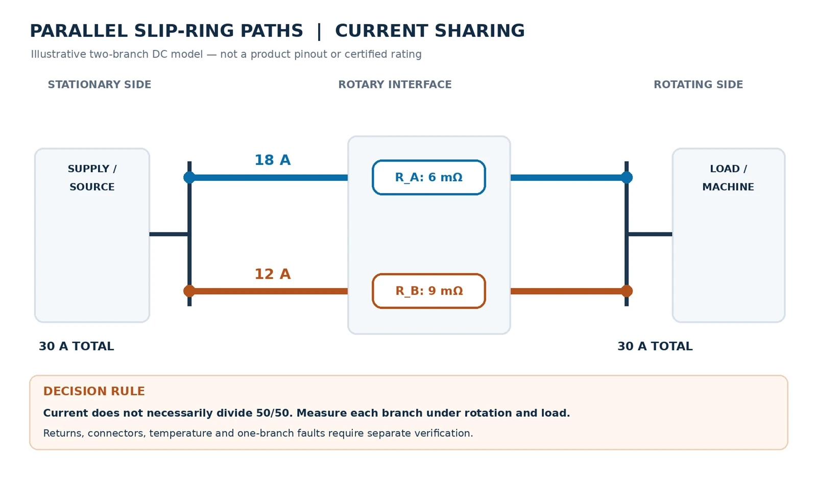
For steady DC current in two idealized resistive paths connected between the same two nodes, each branch carries an inverse-resistance share of the total. If the complete resistance of branch A is RA and that of branch B is RB, the approximation is:
IA = Itotal × RB / (RA + RB); IB = Itotal × RA / (RA + RB).
Consider an illustrative calculation, not ByTune product data: branch A has a complete end-to-end resistance of 6 mΩ, branch B has 9 mΩ and the load draws 30 A DC. The equations give 18 A in A and 12 A in B. An assumed 15 A/15 A split would underestimate current in A by 20%. Suppose the supplier-approved limit happened to be 15 A per branch in this exact installation. The 18 A result would then fail the branch-current acceptance criterion-even though total current is 30 A and before thermal behavior is considered.
| Illustrative quantity | Branch A | Branch B |
|---|---|---|
| Complete branch resistance | 6 mΩ | 9 mΩ |
| Calculated share of 30 A DC | 18 A | 12 A |
| Illustrative branch resistive loss, I²R | 1.94 W | 1.30 W |
| What still needs measurement | Actual branch current, voltage drop, local temperature | Actual branch current, voltage drop, local temperature |
Those resistances include the entire branch as defined in the model; they are not interchangeable with a slip ring's published "electrical noise" or dynamic resistance-variation figure. The calculation is a preliminary sanity check, not a temperature prediction. Heat leaves the contact through a three-dimensional, shared structure, and internal hot spots may not be visible on the housing.
Actual contacts are not constant resistors. Connection resistance, brush pressure, contamination, runout, temperature and wear can change a path during operation. The branch with the lowest initial resistance may carry more load; as contact conditions evolve, the current division may also change. For AC, rectified motor loads and switching waveforms, compare true RMS current and consider impedance, harmonics, transient peaks and branch geometry. The simple DC formula cannot replace those measurements.
Sensitivity check: rerun the numbers when one branch changes
Now suppose branch B increases from 9 mΩ to 12 mΩ while branch A stays at 6 mΩ and the load remains 30 A DC. The idealized network changes from 18 A/12 A to 20 A through A and 10 A through B. Calculated losses become 2.40 W in A and 1.20 W in B, versus the initial 1.94 W and 1.30 W. These are hypothetical whole-branch figures, not tested contact temperatures or ByTune ratings.
| Illustrative condition | Branch A | Branch B | Meaning |
|---|---|---|---|
| 6 mΩ / 9 mΩ initially | 18 A; 1.94 W | 12 A; 1.30 W | Not an equal split |
| B changes to 12 mΩ | 20 A; 2.40 W | 10 A; 1.20 W | Unchanged A carries more current |
| One path becomes open | Remaining path may face the full load until protection acts | Fault response must be verified | |
Unexpectedly, the branch with rising resistance carries less current, while the other branch faces higher loading. Since the assumed resistance includes leads, terminations and sliding contacts, I²R cannot locate the internal hot spot. A nominal 15 A-per-branch limit, if hypothetically specified, would be violated by A in both examples. This calculation is a screening tool; it cannot establish a safe combined rating.
Real loads are not always constant-current. A regulated voltage source, pulsed motor drive or current-limited supply may respond differently as resistance changes. Reassess the actual source and load, then confirm current division and temperature through dynamic tests.
Heating, shared thermal limits and the single-branch failure case
Electrical loss and thermal coupling
At a fixed branch resistance, local electrical loss grows with the square of current: doubling current in one unchanged resistive path produces four times the I²R loss. That does not mean the local temperature rises fourfold. Several adjacent energized circuits can heat the same contact stack, conductors, housing and insulation system, while cooling depends on the full installation. Therefore, evaluate the per-branch loss and the combined assembly temperature together, not as independent thermal ratings.
Connector manufacturer TE Connectivity makes a comparable caution for multi-contact battery interfaces: usable overall current capacity is not obtained merely by multiplying a single contact's maximum rating by the number of contacts. See TE's connector current-rating explanation. This is supporting electrical-contact guidance, not a substitute for testing a rotating slip ring.
A valid thermal test includes the actual conductor bundles, connectors, mounting surfaces, adjacent loaded channels, duty cycle, ambient air or enclosure temperature and steady-state operating condition. If a design review needs a standardized approach to ambient-temperature derating, IEC 60512-5-2 describes a test method for electrical connectors; it does not establish an automatic universal derating percentage or certify a slip ring.
What happens if one branch degrades or opens?
Imagine the two 15 A paths from the hypothetical example are expected to carry a combined 30 A. If one path opens while the power supply and load still demand 30 A, the remaining path could be exposed to nearly the entire load current until system protection or control intervenes. This is a failure scenario, not a claim that every load will continue at constant current: current may also collapse, redistribute or change with the power source and load characteristics.
In design review, document the worst credible contact-loss event, the protective device's response, motor-drive behavior, fault detection and whether the machine must enter a safe state. A shared upstream fuse may protect the overall supply without adequately protecting an individual overloaded parallel branch. Branch protection and coordination require qualified electrical design, and a redundant brush or ring arrangement must not be marketed as fault tolerant without a defined fault test.
If the loss of a path would create unacceptable fire, safety or availability risk, the response may be a separately rated higher-current channel, a revised power architecture, suitable monitoring and protection, or an entirely different rotary interface. Parallel wiring is not itself a safety measure.
How to validate a proposed parallel-circuit slip ring
Test the final proposed assembly, not a loose sample ring with temporary jumpers that will disappear in production. A defensible plan compares predicted branch sharing with measured results and checks thermal headroom under the full machine duty cycle.
Instrument the paths individually
Measure the current in each paralleled branch at accessible, documented locations using appropriately rated current sensors with suitable bandwidth and accuracy. Record branch A, branch B and the separately measured total current on a synchronized timeline. For energized testing, measure voltage drop between approved sense points using appropriately isolated, rated equipment. Do not connect an ohmmeter or a normal four-wire resistance meter across a live high-current circuit. On a de-energized and isolated sample, four-terminal resistance measurement can reduce test-lead error; Fluke explains the four-wire measurement principle. A live test requires a different, validated voltage-sensing method and safe access to the measurement points.
Place thermal sensors at approved accessible locations such as terminations and the housing. A thermal camera can help identify visible anomalies, but it cannot directly prove the hidden contact temperature. If the project requires an internal contact-temperature limit, ask the supplier for an instrumented prototype test or validated model.
| Test condition | Record | Approval question |
|---|---|---|
| Static, unloaded baseline | Pinout, continuity, isolation, installation geometry | Are the intended branches and return paths correctly wired? |
| Static, representative load | Current A/B, total current, branch voltage drop, termination temperatures | Is sharing acceptable before motion begins? |
| Continuous rotation at operating speed | Time-synchronized branch currents, temperature trend, voltage drop | Does motion disturb sharing or introduce intermittent events? |
| Start, stop and reversal | Peak current, duration, current redistribution, any power interruptions | Do transients remain within the approved limits? |
| Maximum specified duty at worst relevant ambient | Thermally stabilized temperatures, RMS current, neighboring channel load | Does the finished assembly retain adequate thermal margin? |
| Degraded-path or protective-response test, if safe and approved | Detection and protection timing, remaining-branch current, system response | Is the single-branch event handled safely? |
| Repeat after defined cycling or endurance exposure | Drift in current sharing, voltage drop, wear indicators and temperatures | Do the approved limits remain satisfied as contacts age? |
Acceptance values are project-specific. Agree in writing on the maximum allowable branch current, voltage drop, temperature or temperature rise, duration and permitted transient deviation before testing. Do not select a universal 70%, 80%, or 10°C rule without a relevant approved specification. Include measurement uncertainty, sensor placement and the method used to judge stable thermal conditions.
Turn the matrix into a repeatable test procedure
Before energizing, approve the wiring drawing, branch identification, return path, protection and safe measurement points. Document each current sensor's orientation, calibration, bandwidth and time synchronization. A delayed or averaged reading can conceal a short redistribution event.
- Isolate and identify. Under the required de-energization procedure, verify ring assignments, insulation and the intended joining points. Four-wire resistance checks belong on isolated circuits, not energized power paths.
- Establish the stationary baseline. Apply the approved test load, capture both branch currents and an independent total, and reconcile any unexplained mismatch within instrument uncertainty.
- Reproduce motion. Record start-up, nominal speed, reversal, load cycling and the specified operating ambient, including neighboring energized channels. Compare peaks and trends, not just averages.
- Confirm thermal and protection behavior. Measure accessible termination and housing temperatures until the agreed stabilization condition. Request manufacturer evidence for inaccessible contact temperatures. Attempt a controlled degraded-branch test only if expressly approved by the hazard analysis and supplier.
- Keep a release record. Preserve synchronized raw traces, sensor positions, abnormal events, test conditions and written supplier disposition.
Acceptance must use agreed branch RMS and peak limits, permitted interruptions, thermal limits and protection response times. A test fails if any approved limit is breached even when the total current looks normal. There is no universal allowable sharing imbalance or temperature-rise threshold for every slip ring.
When not to parallel the channels
Do not approve a retrofit merely because unused wires are physically present. Common reasons to stop are:
- There is no manufacturer approval or complete channel drawing for the exact assembly.
- The proposed extra channels were designed for signals, a different voltage class, protective bonding or another separate function.
- The stationary and rotating terminations cannot be joined symmetrically and inspected reliably.
- Individual branch currents cannot be measured or the thermal limit of internal contacts is unknown.
- The machine's peak, fault or ambient conditions exceed the evidence supporting the arrangement.
- One branch losing contact could overload the remaining path before protection acts.
- The design has no credible way to validate the installed configuration at operating speed.
For a new high-current machine, a carbon-brush slip ring product family or a custom power-transfer design may be a better starting point than combining spare low-current channels. The preferred architecture depends on the operating current, voltage, mounting envelope, speed, duty cycle and maintenance plan-not simply the number of free rings.
For adjacent tasks, ByTune's temperature-rise article covers broader thermal causes and its contact-resistance guide addresses measurement interpretation. Neither page should be treated as authorization to wire a specific model in parallel.
What to send the supplier before connecting anything
Send the supplier a one-page circuit schedule and an explicit request for written approval. A useful engineering inquiry states which rings would be joined, rather than asking only whether the company "supports 30 A."
| Specification field | Information to supply |
|---|---|
| Application and motion | Stationary/rotating equipment, normal/max RPM, start-stop-reversal profile, duty and service target |
| Electrical service | AC/DC, supply voltage, continuous RMS current, peak/inrush waveform and duration, load type |
| Proposed parallel group | Exact model/drawing revision, ring IDs, number of proposed branches and both joining points |
| Complete circuit plan | Supply, return, phases, neutral as applicable, protective earth, signal channels and nearby loaded rings |
| Termination details | Wire size and length, connectors, splices, busbars, strain relief and cable routing |
| Installation environment | Ambient/enclosure temperature, ventilation, sealing, vibration and mounting arrangement |
| Safety and validation | Protective devices, branch-loss response, branch-current limits, thermal limits and required test records |
Ask the supplier to confirm whether the proposed branch grouping is allowed, what the combined current rating is under your specified conditions, which wiring is approved and how the value was validated. A drawing showing current paths and tested temperature points is more useful than a generic assertion that circuits are "parallel-capable." For a named ByTune model, the required approval must be based on that model's actual drawing and data; a product-family web page is not sufficient.
The decision: approved parallel group or dedicated high-current path?
Parallel circuits can be a legitimate way to transfer additional current when their complete electrical and thermal behavior is deliberately engineered. If the exact assembly supports the arrangement, each branch carries acceptable current throughout the relevant duty, terminations and shared housing remain within their thermal limits, and the machine handles credible faults, the design has a basis for approval.
Retrofit or new machine: choose the architecture, not just an extra wire
A spare ring in an installed machine is not automatically spare current capacity. Aging contacts, unequal cable lengths, inaccessible junctions and uncertain drawing revisions can make a retrofit difficult to authorize, even when a brief bench test appears satisfactory.
| Situation | Critical check | Preferred decision path |
|---|---|---|
| Retrofit with spare power-rated rings | Exact revision, approved grouping, safe access, dynamic branch currents and protection | Validate the approved parallel group or replace the assembly |
| Retrofit with signal-only spares | No proven power-circuit rating | Do not repurpose them; select a suitable power path |
| New machine with higher known load | Waveforms, returns, envelope, duty and serviceability | Compare dedicated high-current contact with a manufacturer-engineered group |
New equipment offers the opportunity to specify a purpose-rated high-current circuit from the outset, simplifying wiring and fault accountability. A manufacturer-engineered parallel arrangement may still be viable if its total capacity and failure behavior have been tested. For either option, compare the same load profile, mechanical envelope, evidence requirements and maintenance access. Hardware price alone is not a complete engineering comparison.
Release or hold: the evidence-based decision matrix
| Decision | Evidence required | Action |
|---|---|---|
| Approve for the defined application | Written approval for the exact model, revision, ring IDs and both joining points; each branch and return within stated limits through the complete dynamic duty; documented temperatures and protective response meet pre-agreed acceptance criteria | Release only that documented configuration and duty cycle. |
| Hold for engineering review | Unknown branch-current split, inaccessible thermal limit, missing wiring drawing, untested ambient or motion condition, or ambiguous fault response | Do not connect or energize a parallel retrofit. Request additional manufacturer evidence or redesign and retest. |
| Use a dedicated higher-current design | No manufacturer authorization; any branch exceeds its allowed current; the shared assembly overheats; or a credible path loss creates an unacceptable hazard | Choose a purpose-rated channel or have the manufacturer engineer a different rotary power architecture. |
If any of those conditions cannot be demonstrated, the responsible answer is not to add another wire and hope for equal sharing. Use a purpose-rated high-current path or ask the manufacturer to evaluate a custom rotary-power architecture. The meaningful rating is the verified performance of the complete rotating assembly-not the arithmetic sum of individual circuit labels.