


How Does Pancake Slip Ring Connector Install?
Pancake slip ring connectors install by securing the stator disc to a fixed surface using bolts or mounting brackets, then aligning the rotor disc with the rotating shaft and fastening it with set screws. The two plates must maintain proper spacing (typically 5-6mm apart) to ensure spring contacts maintain consistent pressure on the conductive rings.
Understanding Pancake Slip Ring Connector Structure Before Installation
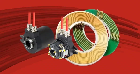
A pancake slip ring consists of two primary components that face each other in a flat, disc-like configuration. The rotor plate contains concentric circular contact rings arranged radially, with each ring soldered to color-coded cables extending from one side. The stator plate houses spring-loaded brushes-often double or quadruple contacts-that press against these rotating rings to maintain electrical continuity during 360-degree rotation.
This pancake slip ring connector design differs fundamentally from cylindrical slip rings. Instead of transferring signals along a shaft's length, pancake models transfer them perpendicular to the rotation axis. Manufacturing quality matters significantly: precious metal contacts (typically gold-plated) ensure low electrical noise and resistance, while the PCB-based construction allows thickness as minimal as 6mm. The separate rotor-stator design permits flexible integration into space-constrained systems where vertical clearance is limited but horizontal diameter is less restrictive.
Pre-Installation Preparation and Requirements
Gathering Necessary Tools and Materials
You'll need basic mechanical and electrical tools for proper installation. Standard requirements include Allen wrenches or hex keys matching the slip ring's set screw sizes, screwdrivers (flathead and Phillips), mounting brackets or flanges if not pre-installed, and wire crimpers for electrical connections. Add a multimeter for testing continuity and alignment tools or calipers for precise positioning.
For hardware, gather appropriate fasteners-typically M3 or M4 bolts with flat washers. If using lock washers, place flat washers between them and the mounting flange to prevent component damage. The manufacturer rarely includes fasteners, so verify thread specifications beforehand. For applications requiring environmental protection, prepare weatherproof housing or IP-rated enclosures.
Inspecting the Slip Ring Components
Before beginning installation, conduct a thorough visual inspection. Examine both rotor and stator plates for any shipping damage, scratches on contact surfaces, or bent spring brushes. Check that all lead wires are securely soldered and properly color-coded-matching colors typically indicate paired connections that transmit signals through the same ring.
Verify the through-bore diameter matches your shaft specifications. Standard pancake slip rings come in bore sizes ranging from 12.7mm to 50mm, with some manufacturers offering larger custom options up to 500-1000mm for industrial applications. Measure shaft diameter precisely; a slip fit is minimum requirement, though bushings can adapt between standard bore sizes.
Test electrical integrity before installation using a multimeter. Measure insulation resistance between circuits (should exceed 100MΩ at 500VDC) and verify continuity through each ring-brush pair. This baseline testing helps identify manufacturing defects before they're obscured by installation.
Evaluating the Installation Environment
Assess mounting location carefully, as environmental factors critically affect pancake slip ring performance. These components tolerate operational speeds up to 300 rpm maximum-significantly lower than cylindrical designs. Applications requiring higher speeds risk premature failure from excessive centrifugal forces and vibration-induced damage to the flat disc structure.
Consider temperature ranges. Most pancake slip rings operate reliably between -20°C and +80°C, though some military-grade units extend from -40°C to +75°C. Confirm your application falls within specifications. For installations in humid or dusty environments, verify the protection grade; standard models offer IP40 or IP54, while higher ratings (IP51, IP65) require sealed housings.
Space constraints dictate pancake slip ring selection. Measure available vertical clearance-pancake designs excel where height is restricted but diameter isn't critical. However, their wide footprint may pose challenges in radially constrained spaces. Ensure adequate clearance for both the slip ring body and cable routing without creating tension or side-loading on the unit.
Step-by-Step Pancake Slip Ring Connector Installation Process
Positioning and Aligning the Stator
The stator typically remains stationary during operation, so it mounts to the fixed portion of your equipment. For flange-mounted designs, position the stator flange against a clean, flat mounting surface. Misalignment at this stage propagates through the entire assembly, causing uneven wear and potential failure.
Align mounting holes precisely with corresponding holes on your equipment base. Use alignment tools or dowel pins if available to maintain positioning while inserting fasteners. Start all bolts finger-tight before final tightening to allow minor position adjustments. Tighten bolts in a cross-pattern (like wheel lug nuts) to distribute pressure evenly and prevent warping.
For installations without dedicated flanges, the slip ring body may require custom brackets. Design brackets to support the stator rigidly without introducing stress concentrations. Some miniature pancake models can be mounted by securing the stator lead wires directly or by pressing the outer housing into a precisely sized hole in the mounting plate.
Critical: Do not "hard mount" both rotor and stator with zero compliance. This means avoiding configurations where both components are rigidly fixed with no mechanical flexibility. Hard mounting prevents the slip ring from accommodating minor eccentricities and misalignments during rotation, often causing premature bearing failure or contact damage. Always allow the rotor some floating capability relative to the stator.
Securing the Rotor to the Rotating Shaft
The rotor mounts to the rotating component-typically a shaft, turntable, or rotating platform. For through-bore installations, clean the shaft surface thoroughly using non-residue solvent cleaner. Remove any rust, debris, or old lubricants that could prevent secure mounting or cause runout issues.
Slide the rotor onto the shaft, aligning the bore concentrically. For shafts between standard bore sizes, use bushings to achieve proper fit. Position the rotor at the desired location along the shaft length, ensuring sufficient clearance from adjacent components and providing adequate space for cable routing.
Secure the rotor using set screws located on the rotor hub. Pancake slip rings typically feature 2-4 set screws positioned around the bore circumference. Tighten set screws evenly in stages-bring each screw to light tension, then tighten them gradually in rotation. This prevents cocking the rotor on the shaft. Position set screw mechanisms 180 degrees apart on a single ring to minimize shaft unbalancing.
For applications under 5 rpm, the rotor lead wires can function as a flexible coupling, eliminating the need for separate coupling hardware. Above this speed, employ a dedicated flexible coupling-rubber tubing, heat-shrink tubing, spiral couplings, or bellows-type couplings-between the rotor and shaft. This accommodation for slight misalignments prevents mechanical stress transfer to the slip ring's precision bearings.
Establishing Proper Spacing Between Rotor and Stator
Contact pressure between spring brushes and conductive rings is controlled by the axial distance separating the two plates. This spacing is critical to slip ring performance: too wide reduces contact pressure, causing intermittent connections and increased electrical noise; too narrow overloads the brushes, accelerating wear.
Standard pancake slip rings specify optimal spacing around 5.8-6mm after installation, though this varies by model and manufacturer. Some designs include built-in spacers or mechanical stops that establish correct spacing automatically when properly assembled. For separate-type pancake slip rings (where rotor and stator install independently), you must measure and maintain this gap manually.
Use feeler gauges or precision spacers to verify spacing uniformly around the ring's circumference. Check at multiple points-90-degree intervals minimum-to detect any tilt or misalignment between plates. Adjust mounting positions incrementally until consistent spacing is achieved.
The spring contacts must maintain consistent pressure across all rings simultaneously. Uneven spacing causes some contacts to press too hard while others barely touch, creating unreliable signal transmission. This adjustment represents the most critical aspect of pancake slip ring installation success.
Wiring and Electrical Connections
Pancake slip rings simplify wiring through color-coded lead pairs. Incoming and outgoing cables of identical colors connect through the same slip ring circuit, minimizing confusion during installation. This means if the rotor has a red wire and the stator also has a red wire, these two wires complete one circuit through their associated ring and brush.
Route stator leads away from the rotation axis to prevent entanglement with moving components. Secure stator wiring to the fixed equipment structure using cable ties or clamps, providing strain relief to prevent mechanical stress on solder joints. Leave sufficient slack for thermal expansion but avoid excess that could snag during operation.
Rotor leads require special consideration since they rotate with the shaft. Route rotor wiring away from the fixed portion of the equipment. For slow-speed applications (under 5 rpm), rotor leads can extend freely, but ensure they don't contact stationary surfaces during rotation. Above 5 rpm, manage rotor leads with cable carriers, spiral wraps, or by routing them through the hollow shaft if using a through-bore design.
Make electrical connections according to your application requirements. Use appropriate connectors-crimp terminals, solder joints, or terminal blocks-ensuring connections are mechanically and electrically sound. Protect all exposed conductors with heat-shrink tubing or electrical tape. For high-frequency or data signals, maintain proper shielding and grounding to minimize electromagnetic interference.
Installing Anti-Rotation Mechanisms
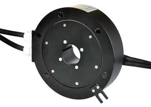
Most pancake slip rings include anti-rotation tabs or devices to prevent the stator from rotating during operation. These mechanisms are essential: if the stator rotates even slightly, it defeats the slip ring's purpose and creates stress on stationary wiring.
Anti-rotation devices vary by design. Common types include:
Fixed tabs: Small protrusions on the stator housing that align with corresponding holes on the mounting surface. Insert a screw or dowel pin (not typically supplied) through the tab into the fixed surface.
Torque arms: Extended brackets on the stator that bolt to the equipment frame, mechanically preventing rotation while allowing the necessary compliance for shaft eccentricity accommodation.
Clamp-style restraints: Separate components that grip the stator housing and anchor to nearby fixed structures.
Install the anti-rotation mechanism after both rotor and stator are positioned but before final torquing of all fasteners. This sequence allows fine-tuning alignment while ensuring the stator cannot rotate once everything is secured. Verify the mechanism engages properly without binding or creating excessive force on the slip ring housing.
Testing and Verification After Installation
Initial Electrical Testing
Before applying operational loads, conduct baseline electrical tests to verify installation quality. Start with continuity testing: use a multimeter set to continuity or low-resistance mode, and verify each circuit passes current from rotor lead to corresponding stator lead. Resistance should be low (typically under 0.5Ω) and consistent across all circuits.
Measure insulation resistance between circuits using a megohmmeter or multimeter capable of 500VDC testing. Properly installed pancake slip rings show insulation resistance exceeding 100MΩ between any two circuits. Lower readings indicate potential contamination, moisture intrusion, or damaged insulation requiring immediate investigation.
Test contact quality dynamically by rotating the slip ring slowly by hand while measuring resistance across one circuit. Resistance should remain stable throughout rotation with minimal fluctuation (under 5mΩ variance). Significant spikes indicate poor brush contact, contamination on ring surfaces, or improper spacing between plates.
For signal applications, inject a test signal (appropriate to your application-audio, video, data, or power) and monitor output while rotating the slip ring. Look for signal degradation, intermittent dropouts, or electrical noise that might indicate installation problems. High-frequency or data signals are particularly sensitive to contact quality issues.
Mechanical Alignment Verification
Proper mechanical alignment ensures long service life and reliable operation. Rotate the slip ring manually through several complete revolutions, feeling for any binding, roughness, or uneven resistance. Smooth, consistent rotation indicates good alignment; any irregularity suggests misalignment problems requiring correction.
Listen for unusual sounds during rotation. Properly installed pancake slip rings operate nearly silently at low speeds. Clicking, scraping, or grinding noises indicate mechanical interference-possibly from misaligned components, debris in the contact area, or overtightened fasteners causing warping.
Check for runout using a dial indicator positioned against the rotor face or outer diameter while rotating the shaft. Excessive runout (typically over 0.1mm for precision applications) indicates bent components, improper mounting, or shaft problems. Runout causes cyclic variation in contact pressure, accelerating brush wear and creating electrical noise.
Verify there's no axial or radial load on the slip ring bearings. Pancake slip rings are not designed to support external mechanical loads-the rotating equipment must be independently supported. Apply gentle force axially and radially to the rotor; if you detect any shaft displacement or bearing preload, the installation places improper stress on the slip ring, requiring support structure modifications.
Environmental Protection Verification
If your application requires environmental protection, verify sealing integrity after installation. For IP-rated housings, ensure gaskets seat properly, drain holes (if present) orient correctly, and all cable entry points use appropriate glands or sealants. Improper sealing allows moisture and dust infiltration, the leading causes of premature slip ring failure.
For outdoor installations, confirm the slip ring installs within a weatherproof enclosure. Even IP65-rated slip rings benefit from additional protection against direct weather exposure, temperature extremes, and UV radiation. Position the enclosure to prevent water accumulation and provide adequate ventilation if the slip ring generates heat during operation.
In high-vibration environments, reverify all fastener torque after initial testing. Vibration can loosen connections that seemed secure during static installation. Consider using thread-locking compounds on critical fasteners, though consult manufacturer guidelines first as some compounds damage slip ring materials.
Common Installation Problems and Solutions
Misalignment Issues
Misalignment between rotor and stator ranks among the most frequent installation problems. Symptoms include uneven brush wear, increased friction, intermittent electrical connections, and premature failure. Misalignment typically stems from improper mounting surface preparation, overtightened fasteners causing component warping, or shaft eccentricity exceeding the slip ring's tolerance.
To correct misalignment, first identify the source. Loosen all mounting fasteners and observe whether the rotor positions itself more centrally relative to the stator when allowed to float. If so, the mounting surface may not be perpendicular to the shaft axis, or fasteners were overtightened. Ensure the mounting surface is flat within 0.05mm across its diameter and perpendicular to the rotation axis.
For shaft-induced misalignment, implement a flexible coupling between the shaft and rotor, even if operating under 5 rpm. Flexible couplings accommodate angular, parallel, and axial misalignments that rigid connections cannot tolerate. Select coupling types appropriate for your misalignment magnitude and operational speed.
If misalignment persists despite these measures, the shaft itself may be bent or running untrue. Verify shaft runout separately from the slip ring installation. Correcting shaft problems often requires bearing replacement, shaft straightening, or equipment realignment-issues beyond slip ring installation scope but critical to successful operation.
Electrical Noise and Signal Interference
Electrical noise in pancake slip ring systems manifests as signal degradation, intermittent connections, or electromagnetic interference with nearby electronics. Multiple factors contribute: contamination on contact surfaces, inadequate shielding, improper grounding, or external electromagnetic sources.
Start by cleaning contact surfaces if contamination is suspected. Disassemble the slip ring and clean both rings and brushes with non-residue solvent cleaner specifically approved for electrical contacts. Avoid petroleum-based products that leave residue. For stubborn deposits, use 600-grit or finer abrasive-never coarse materials that damage precious metal plating.
Internal interference between circuits requires specialized wiring. If high-frequency signals experience crosstalk with power circuits, consult the manufacturer about slip rings with internal shielding between circuit groups. Some applications demand complete circuit redesign with separate slip rings for power and signals to achieve necessary isolation.
External electromagnetic interference requires shielding at the system level. Route slip ring cables away from high-current power lines, motor drives, and other EMI sources. Use shielded cables for sensitive signals, ensuring shields connect properly to ground at one end only (typically the stationary stator side) to prevent ground loops. In severe cases, install the entire slip ring assembly within a grounded metal enclosure providing Faraday cage protection.
Mechanical Binding or Rough Rotation
If the slip ring rotates roughly or binds during operation, immediate investigation is essential to prevent damage. Common causes include overtightened set screws deforming the rotor hub, debris between contact surfaces, damaged bearings, or excessive side-loading from improperly routed cables.
Begin by disconnecting power and manually rotating the slip ring. If binding occurs at specific rotational positions, suspect debris or damage at those locations. Disassemble the unit carefully, examining all surfaces for foreign material, scratches, or deformed components. Clean thoroughly and replace any damaged parts.
Check set screw torque-overtightening compresses the rotor hub, distorting it out of round. This distortion causes binding as the deformed section rotates past the stator brushes. Loosen set screws completely, verify the rotor rotates freely, then retighten gradually using a calibrated torque driver to manufacturer specifications. Most pancake slip ring set screws require surprisingly little torque (often 1-3 Nm).
Verify cable routing doesn't create side-loading. Cables must have sufficient slack and proper strain relief to avoid pulling laterally on the slip ring body during rotation. Side-loading quickly damages precision bearings designed only for rotational loads. Reroute cables if necessary, adding cable carriers or spring-tensioned cable management systems for applications with multiple rotations in one direction.
Intermittent Connectivity
Intermittent electrical connections frustrate troubleshooting because symptoms appear sporadically. Causes range from poor brush contact pressure to vibration-induced connection problems to thermal expansion issues at solder joints.
Verify proper rotor-stator spacing first, as incorrect spacing is the primary cause of intermittent contact. Measure the gap at multiple points around the circumference while slowly rotating the slip ring. Variation exceeding 0.5mm indicates tilt between plates requiring correction through mounting adjustment.
If spacing is correct, inspect brush spring tension. Brushes lose tension over time or may arrive from the factory with insufficient pressure. Some designs allow brush tension adjustment; consult manufacturer documentation. Brushes showing signs of wear, damage, or contamination require replacement-typically available as service kits matched to specific slip ring models.
Temperature cycling sometimes causes intermittent connections through thermal expansion mismatches. Materials expand at different rates as temperature changes, potentially opening connections at solder joints or between components. This issue particularly affects installations spanning wide temperature ranges. Solutions include using strain relief on all connections, applying flexible solder (lower melting point alloys), or selecting slip rings designed specifically for your temperature range.
Maintenance Best Practices for Installed Pancake Slip Rings
Regular maintenance extends slip ring life significantly. Manufacturers often specify service intervals, but typical recommendations include visual inspection every 500 operating hours or monthly for continuous-duty applications. During inspection, check for visible wear on contact surfaces, damaged or frayed cables, loose fasteners, and any signs of moisture or contamination intrusion.
Cleaning frequency depends on environmental conditions. Clean operating environments may require cleaning only annually, while dusty or contaminated settings need quarterly or more frequent cleaning. Use only approved cleaners-non-residue solvents specifically formulated for electrical contacts. Never use abrasive cleaning methods on precious metal surfaces as they remove the gold or silver plating exposing base metal underneath.
Brush replacement timing varies by duty cycle, current load, and environmental factors. Manufacturers typically specify service life in hours or revolutions-commonly 50 million revolutions for quality pancake slip rings. Monitor brush wear during regular inspections; replace brushes when they've worn to approximately half their original length to maintain consistent contact pressure.
Re-torque all fasteners during the first maintenance interval after installation (approximately 100 operating hours). Initial operation often allows components to settle, potentially loosening connections that were tight initially. After this first check, fastener verification can extend to longer intervals unless operating in high-vibration environments requiring more frequent monitoring.
Pancake slip ring connectors demand careful attention during installation but reward precision with reliable, long-lasting performance. The flat disc design solves height-restricted applications that cylindrical slip rings cannot accommodate, making them irreplaceable components in robotics, CCTV systems, rotating stages, and countless automation applications. Proper installation techniques-precise alignment, correct spacing, appropriate torque values, and careful cable management-ensure these compact power and signal transmission devices deliver their full potential across millions of rotations.
Frequently Asked Questions
What's the maximum rotational speed for pancake slip ring installations?
Most pancake slip rings are limited to 300 rpm maximum operational speed. The flat disc design experiences higher centrifugal forces compared to cylindrical types, making them susceptible to vibration damage at higher speeds. Applications requiring speeds above 300 rpm typically require cylindrical slip ring designs instead. Always verify speed specifications with the manufacturer before installation, as some specialized pancake designs may offer different ratings.
Can I install a pancake slip ring in any orientation?
Pancake slip rings are bidirectional and generally orientation-agnostic, meaning they can mount horizontally, vertically, or at any angle without affecting electrical performance. However, mounting orientation affects dust accumulation and moisture drainage. Vertical installations with the stator on top better prevent debris from settling on contact surfaces. For humid environments, orient the unit to allow any condensation to drain away from electrical contacts rather than pooling within the housing.
How do I know if my shaft is compatible with the slip ring bore size?
Measure your shaft diameter precisely using calipers, then compare against the slip ring's specified bore size. The slip ring should slide onto the shaft with minimal clearance-a slip fit rather than loose or requiring force. Standard pancake slip ring bores are 12.7mm, 25.4mm, 38.1mm, and 50mm, though custom sizes are available. If your shaft diameter falls between standard sizes, use a bushing adapter to match the slip ring bore to your shaft. Never force a slip ring onto an oversized shaft as this deforms the bore and damages bearings.