

Choosing a through bore slip ring is not just about matching a hole size to a shaft. The bore diameter gets most of the attention during early selection, but in engineering reviews, the most common source of problems is not the bore itself - it is incomplete circuit definition, underestimated thermal load, or a mismatch between the operating environment and the housing protection level.
A through bore slip ring - also referred to as a hollow shaft slip ring or through hole slip ring - features an open center that allows a shaft, pneumatic line, hydraulic tubing, fiber optic cable, or wire bundle to pass through while power and signals transfer between stationary and rotating structures. This guide covers the full selection process: bore sizing, circuit planning, signal protection, environmental matching, cost factors, and supplier evaluation, so that engineers and procurement teams can define their requirements before requesting a quote.

Quick Selection Summary
If you need a fast overview before reading the full guide, here are the core decisions that shape every through bore slip ring selection:
- Bore diameter and mechanical envelope - Sized to the shaft or cable bundle, with realistic clearance for assembly and service.
- Circuit count and signal types - Every electrical path defined by function, not just wire count.
- Voltage, current, and peak load - Including startup inrush, not only steady-state values.
- Signal integrity requirements - Shielding, separation, and impedance control for Ethernet, encoder, or other sensitive data.
- IP rating and environmental protection - Matched to the actual installation, not the ideal condition.
- Standard or custom design - Based on a clear set of decision rules, not cost alone.
- Supplier capability - Drawing review, signal validation, and production consistency, not just price.
What Is a Through Bore Slip Ring and How Does It Work?

A through bore slip ring is a rotary electrical connector with a hollow center. It works the same way as other slip rings - brushes or contacts ride against rotating rings to transfer power or signals across a rotating interface - but its distinguishing feature is the open bore running through the center axis.
That central bore can accommodate a drive shaft, a support column, pneumatic or hydraulic tubing, a fiber optic cable, additional wiring, or a mechanical alignment structure. This makes through bore slip rings especially useful in systems where the rotating axis already contains mechanical or fluid components. Instead of routing cables around the outside of the machine, the designer can keep the layout compact and centered.
Common applications include robotic joints and ROV systems, rotary tables and indexing machines, packaging and filling equipment, CCTV pan-tilt platforms, medical imaging and scanning systems, radar and antenna platforms, cable reels, and any rotating assembly that combines electrical transmission with pneumatic, hydraulic, or optical routing.
Through Bore Slip Ring vs. Other Slip Ring Types
Before committing to a through bore design, it is worth confirming that this mechanical format is the right fit. Engineers sometimes default to a through bore slip ring when a more compact option would work, or they try to force a capsule slip ring into an application that actually needs central routing.

| Slip Ring Type | Best For | Main Advantage | Typical Limitation |
|---|---|---|---|
| Through bore slip ring | Systems with a shaft, tubing, or cable bundle through the center | Open center for mechanical or fluid routing | Larger outside diameter than compact designs |
| Capsule slip ring | Small devices with limited space and no central routing need | Compact size, lower cost | No usable central bore |
| Pancake slip ring | Applications with very short axial space | Low-profile, flat disc structure | May have higher contact wear or speed limitations |
| Hybrid slip ring | Systems combining electrical, pneumatic, hydraulic, RF, or fiber optic transmission | Integrates multiple media into one assembly | Usually requires custom engineering |
For a more detailed comparison, see through bore slip ring vs. capsule slip ring. A through bore slip ring is not always the smallest or cheapest option - its value lies in mechanical integration. If your rotating axis needs a clear center path, it often simplifies the entire machine design.
Step 1: Define the Application and Motion Requirements

Start with the machine, not the catalog.
Before comparing models, define the equipment type, rotation mode (continuous or intermittent), operating speed in RPM, daily operating hours, rotation direction (one-way or reversing), exposure to vibration or shock, and accessibility for maintenance. A slip ring used on a slow-rotating display table has fundamentally different demands from one installed in a high-duty robotic arm or an outdoor surveillance platform that runs around the clock.
The more demanding the duty cycle, the more important contact design, bearing quality, sealing, and lifecycle testing become. If the rotation speed exceeds standard ranges, signal noise and mechanical wear increase - this is where contact material and ring surface finish start to matter as much as electrical specifications.
Application-Specific Considerations
Different industries emphasize different parameters. In robotics, the priorities are typically compact size, low weight, encoder feedback stability, and vibration resistance. Packaging machinery often demands washdown-rated housings, dust protection, and high duty-cycle durability. CCTV and pan-tilt systems focus on IP-rated compact assemblies that carry video signals cleanly. Medical imaging equipment requires exceptional reliability, low electrical noise, and thorough documentation for regulatory compliance.
Identifying the application early helps narrow the field before detailed specification begins.
Step 2: How to Size the Bore Diameter and Mechanical Envelope
The bore diameter is the most visible specification, but it should never be selected in isolation.

Define the required inner bore diameter based on the shaft, cable bundle, or tubing that must pass through. Then confirm the maximum allowable outer diameter, body length, mounting style (flange, shaft, end-of-shaft, or custom bracket), cable exit direction, and available space for connectors or flying leads.
A common engineering mistake is to choose a bore that is barely large enough. In practice, you need clearance for cable jacket thickness, tubing tolerances, shaft runout, assembly variation, and future service access. At the same time, oversizing the bore without reason increases the outer diameter, weight, cost, and starting torque.
Mounting method matters more than many engineers expect early in design. A flange-mounted unit distributes load differently than a shaft-clamp installation, and the choice affects cable routing, vibration response, and long-term reliability. For guidance on mounting approaches, review the installation instructions before finalizing the mechanical layout.
Step 3: How Many Circuits Do You Need?
One of the most frequent errors in slip ring specification is defining circuits by wire count rather than by function. Telling a supplier "I need 12 wires" provides far less useful information than a circuit list like this:
- 2 circuits for 24V DC control power
- 2 circuits for three-phase motor power
- 4 circuits for incremental encoder feedback
- 2 circuits for CAN bus communication
- 4 circuits for analog sensor signals
- 1 shielded Ethernet channel
- 2–3 spare circuits for future expansion
Each circuit should be assigned a function, voltage, current, wire type, and shielding requirement. This level of detail is especially important when power, control signals, and high-speed data share the same assembly, because it determines how the supplier separates channels to control crosstalk and noise. For more on channel design principles, this is worth reviewing before finalizing the circuit list.
Adding a few spare circuits is almost always a good investment. If the machine may later need additional sensors, an extra control axis, or updated feedback lines, spare circuits prevent a full mechanical redesign.
Step 4: How to Specify Voltage, Current, and Thermal Load
Electrical load is where selection errors most often lead to premature failure.

For each power circuit, the specification should include rated voltage, rated current, peak current, startup or inrush current, duty cycle, acceptable voltage drop, and wire gauge. A motor may draw several times its rated current during startup. If the slip ring is sized only to the normal running current, the contacts can overheat, the insulation can degrade, and service life drops sharply.
For high-current applications, pay attention to conductor cross-section, contact material and pressure, temperature rise under load, insulation clearance distances, and whether parallel circuits are needed to divide the load. For guidance on managing heat in through bore designs, see how to control temperature rise in through bore slip rings.
For low-power signal circuits, the concern is usually not heat but contact resistance stability, electrical noise, and signal continuity. This is where channel separation and contact design become the primary selection factors rather than conductor size.
Step 5: How to Protect Signal Quality in a Through Bore Slip Ring
Many through bore slip rings carry both power and data in the same assembly. This is where poor selection causes the most difficult-to-diagnose problems - intermittent encoder feedback errors, network dropouts under motor startup, or video noise that only appears during certain rotation angles.

Sensitive signal types that require careful design attention include incremental and absolute encoder feedback, thermocouple signals, CAN bus, RS-485/RS-422, Ethernet (10/100/1000 Mbps), USB, HD-SDI video, coaxial RF signals, and servo feedback. For these circuits, the key technical factors are shielding effectiveness, twisted-pair routing, impedance matching, contact noise level, crosstalk between adjacent channels, grounding continuity, and physical separation from power channels.
If the encoder signal becomes unstable only when the motor starts, the root cause is usually insufficient separation between power and signal channels. If Ethernet performance degrades during rotation but works fine when stationary, impedance discontinuity across the rotating contact is likely the issue. These are problems that cannot be solved after installation - they must be addressed in the slip ring design. For deeper guidance, see how to ensure stable signal transmission in slip rings.
If the system transmits Gigabit Ethernet, HD video, RF, or optical signals, a standard electrical slip ring may not be adequate. In many high-bandwidth or long-distance transmission applications, a fiber optic rotary joint can provide more stable transmission than routing high-speed data through conventional metal contacts - though this depends on the specific data rate, distance, and noise environment.
Step 6: How to Match IP Rating and Environmental Protection
A through bore slip ring that works reliably in a clean, dry indoor cabinet may fail within weeks in a dusty factory, a washdown food processing line, or an outdoor marine installation. The operating environment directly affects service life, and engineers should match the protection level to the real installation conditions, not the ideal ones.

Define the environment in terms of indoor/outdoor installation, dust and particulate exposure, water spray or washdown frequency, oil, coolant, or chemical exposure, operating temperature range, humidity and condensation, salt spray or corrosion risk, shock and vibration levels, and any cleanroom or medical facility requirements.
IP Rating Reference for Slip Ring Selection
The IP (Ingress Protection) code, defined by IEC 60529, classifies the degree of protection an enclosure provides against solids and liquids. The first digit rates dust protection (0–6); the second rates water protection (0–9). Here is a simplified reference for common slip ring applications:
| IP Rating | Dust Protection | Water Protection | Typical Slip Ring Application |
|---|---|---|---|
| IP40 | Protected against objects >1 mm | None | Clean indoor cabinets, lab equipment |
| IP54 | Dust-protected (limited ingress) | Splash-proof from all directions | Indoor industrial machines with moderate dust |
| IP65 | Dust-tight | Low-pressure water jets from all directions | Packaging machinery, outdoor cameras, light washdown |
| IP67 | Dust-tight | Temporary immersion up to 1 m | Marine equipment, heavy washdown, outdoor platforms |
Always verify the supplier's IP rating claim against the actual test standard and conditions. An IP65 rating tested per IEC 60529 is more reliable than an unverified marketing claim. For more details on interpreting these ratings for slip rings, see understanding slip ring IP ratings.
Also consider mounting orientation. A slip ring mounted vertically, horizontally, or inverted may face different water ingress risks even at the same IP level. Cable exits, shaft seals, and connector protection should be reviewed as part of the complete installation layout.
Step 7: When Do You Need a Custom Through Bore Slip Ring?
Not every project requires a custom design, and not every project can use a standard one. The decision should follow a clear set of rules rather than default assumptions.
A standard model is usually suitable when: the bore size matches a catalog option, the circuit count is moderate with simple signal types, the environment is clean and dry, mounting space is flexible, no unusual connectors are required, and lifecycle requirements fall within typical ranges.
A custom through bore slip ring becomes the better choice when: the system combines power with high-speed signals such as Ethernet, USB, or coaxial channels; the application requires pneumatic or hydraulic integration; the bore size or housing dimensions are non-standard; the environment demands a high IP rating or chemical resistance; the project falls under medical, defense, aerospace, or other regulated industries; or strict lifecycle and documentation requirements apply.
In many OEM integration projects, a custom design actually reduces total risk because the slip ring is built around the real machine layout - rather than forcing the machine to adapt to a catalog part. When the alternative is multiple redesign cycles to accommodate a standard unit, the upfront investment in custom engineering often pays for itself. For a deeper comparison, see standard vs. custom slip rings: which is right for your application.
What Affects Through Bore Slip Ring Cost?
Engineers and procurement teams often ask what drives cost differences between seemingly similar through bore slip rings. While specific pricing depends on the manufacturer and order volume, the following factors consistently influence cost:
- Bore diameter: Larger bores require more material, larger bearings, and more complex manufacturing tolerances. A 100 mm bore unit is significantly more expensive than a 12 mm bore unit, even with the same circuit count.
- Circuit count and current rating: More circuits mean more contact rings, more wiring, and a longer housing. High-current circuits require larger conductors and contact surfaces, which increase both material and assembly cost.
- Signal complexity: Integrating Ethernet, USB, encoder, or RF channels requires precision contact design, controlled impedance paths, and additional testing - all of which add cost compared to simple power-only units.
- IP rating and sealing: Higher IP ratings demand tighter tolerances, additional seals, specialty materials, and more rigorous testing. A sealed IP67 design costs more than an open IP20 design.
- Connectors: Standard flying leads are the most economical cable termination. Custom connectors, military-spec plugs, or specialty interfaces add cost and lead time.
- Testing and documentation: If the application requires individual test reports, material declarations, or compliance documentation (such as RoHS or CE conformity), these add to the unit cost - but they are essential for regulated industries and should not be treated as optional.
- Understanding these cost drivers helps you make informed trade-offs during specification, rather than discovering budget conflicts after the design is locked.
Through Bore Slip Ring Specification Checklist
Before contacting a supplier, prepare the following information. A complete checklist helps the manufacturer recommend the correct design faster and reduces the likelihood of redesign after prototype testing.
| Specification Area | Information to Provide |
|---|---|
| Application | Machine type, industry, function of the rotating assembly |
| Rotation | RPM, continuous or intermittent, direction changes |
| Bore size | Required inner diameter and clearance needs |
| Mechanical envelope | Maximum outer diameter, length, mounting style, cable exit direction |
| Circuit count | Number and function of power, signal, data, and spare circuits |
| Electrical load | Voltage, rated current, peak current, inrush current, duty cycle |
| Signal type | Encoder, Ethernet, CAN bus, USB, coaxial, video, sensor, thermocouple |
| Cable requirements | Wire gauge, shielding, cable length, cable exit direction |
| Connectors | Flying leads, plug-in connectors, terminal blocks, or custom interfaces |
| Environment | IP rating, dust, water, temperature range, vibration, corrosion exposure |
| Lifecycle | Expected operating hours or revolutions, maintenance interval |
| Compliance | RoHS, CE, ISO, medical, defense, or other regulatory requirements |
| Documentation | Drawings, wiring diagram, test report, material declaration, installation guide |
| Quantity | Prototype quantity and expected annual production volume |
Documents to Request from the Supplier
Beyond the specification checklist, experienced engineering teams also request the following documents before approving a through bore slip ring for production use: mechanical drawing with tolerances, wiring diagram and pinout confirmation, electrical test report (contact resistance, insulation resistance, dielectric strength), signal performance test data for Ethernet, encoder, or other high-speed channels, IP test statement referencing the applicable test standard, material declaration or RoHS compliance certificate, and a quality inspection report for batch production. These documents serve as the verifiable basis for engineering approval and help distinguish between a product claim and a tested, documented result.
Common Mistakes in Through Bore Slip Ring Selection
Choosing only by bore size.
The bore diameter is necessary but not sufficient. A slip ring with the correct hole can still fail if the current rating, signal design, sealing, or mounting method is mismatched. In engineering reviews, incomplete circuit definition causes more project delays than incorrect bore size.
Ignoring peak and inrush current.
Many systems draw significantly higher current during motor startup, braking, or short overload events. If the slip ring is rated only for steady-state current, the contacts overheat and the insulation degrades - sometimes within weeks. Always define both rated and peak current, and confirm that the supplier accounts for inrush conditions.
Running power and signal circuits without isolation.
Placing encoder, Ethernet, or sensor signal lines too close to power circuits without shielding or separation creates noise problems that are extremely difficult to troubleshoot in the field. The solution is proper shielding and channel separation, built into the slip ring design from the start.
Underestimating the operating environment.
Dust accumulation, water ingress, oil contamination, vibration fatigue, and thermal cycling all shorten service life. Select the IP rating and housing material for the real working conditions - not for the conditions you hope for. A slip ring rated IP54 will not survive in a washdown environment that actually requires IP65 or IP67.
Neglecting future expansion.
If the machine may eventually need more sensors, an additional communication bus, or a control axis upgrade, it is far more cost-effective to include spare circuits during initial design than to replace the entire slip ring later.
Approving without drawings or wiring documentation.
A slip ring is part of an integrated electrical and mechanical system. Proceeding to production without confirmed drawings, pinout diagrams, cable routing details, and installation instructions increases the risk of assembly errors and field failures.
How to Evaluate a Through Bore Slip Ring Manufacturer
The right manufacturer does more than ship a part number. In engineering practice, supplier capability often matters as much as product specifications - especially for OEM projects where the slip ring will be integrated into hundreds or thousands of machines over multiple years.
Evaluate the supplier's ability to provide engineering consultation during specification, both standard and custom design options, mechanical drawings with revision control, complete wiring diagrams, signal transmission guidance for high-speed or mixed-signal applications, IP-rated housing options tested to recognized standards, lifecycle and performance test data, and consistent quality control from prototype through volume production.
Ask practical, verifiable questions: Can the supplier review your full circuit list before quoting? Can they provide signal test data for Ethernet or encoder channels? Can they customize bore size, lead wire length, connector orientation, or cable exit? Can they supply inspection reports with each production batch? Do they control drawing revisions and pinout confirmation across orders?
A low-cost part that works in a single prototype may not be the right choice if the supplier cannot maintain repeatable quality, accurate documentation, and consistent lead times across production volumes. For a structured approach to manufacturer assessment, see 6 steps to choose a slip ring manufacturer.
Prototype Validation Checklist
Before approving a through bore slip ring for production, engineering teams should validate the unit under conditions that represent the actual application - not just bench-test it in ideal conditions. A practical validation process includes:
- Mechanical fit check: Verify bore clearance, outer diameter, body length, mounting alignment, cable exit routing, and connector access with the real machine assembly.
- Electrical load test: Run the slip ring at rated and peak current for a representative duty cycle. Measure contact resistance, voltage drop, and temperature rise under load.
- Signal integrity test: For Ethernet, encoder, USB, or other sensitive channels, test signal performance during rotation at operating speed. Check for packet loss, bit errors, or signal degradation that only appears under dynamic conditions.
- Environmental exposure: If the application involves dust, moisture, temperature extremes, or vibration, test the prototype under those conditions - or at minimum confirm the supplier's environmental test data against the relevant standard.
- Lifecycle sampling: Request the supplier's lifecycle test conditions and results. A stated lifetime of "50 million revolutions" means little without knowing the test speed, load, temperature, and pass/fail criteria. Ask for the test conditions, not just the number.
Validation costs time and resources, but it is far less expensive than a field failure that requires a redesign after production has started.
Frequently Asked Questions
What is the difference between a through bore slip ring and a capsule slip ring?
A through bore slip ring has an open center for shaft or cable routing. A capsule slip ring is more compact and typically more economical, but it does not provide a usable central bore. Capsule slip rings work well in smaller devices without central routing needs; through bore slip rings are the better choice when the rotating axis must accommodate mechanical or fluid components through the center.
Can a through bore slip ring transmit Ethernet or USB signals?
Yes, but high-speed data transmission requires specific design attention. Ethernet, USB, encoder, and video signals need controlled impedance, shielding, and separation from power channels. For Gigabit Ethernet or high-definition video, a dedicated Ethernet slip ring or a hybrid assembly with a fiber optic rotary joint may be the more reliable solution. Always ask the supplier for signal test data specific to your data rate and protocol.
How do I choose the right bore size?
Start with the actual shaft, tube, or cable bundle that must pass through the center. Measure its maximum outside diameter, then add clearance for cable jacket thickness, assembly tolerance, shaft runout, and future service access. As a practical guideline, at least 2–3 mm of radial clearance beyond the maximum component diameter is a reasonable starting point for most industrial applications, though more demanding installations may need more.
When should I choose a custom design instead of a standard model?
Consider custom engineering when the application involves a non-standard bore size, mixed power and high-speed data circuits, high IP rating requirements, unusual connectors, pneumatic or hydraulic integration, regulated industry compliance (medical, defense, aerospace), or strict lifecycle documentation. Many OEM projects benefit from custom designs because the slip ring fits the machine - rather than the machine being forced to adapt to catalog limitations.
What information should I include in an RFQ for a through bore slip ring?
A complete RFQ should include the application description, bore diameter, RPM, rotation mode, full circuit list with function and load per circuit, signal types and data rates, cable length and termination type, IP rating requirement, operating environment details, mounting style, lifecycle expectation, compliance requirements, and expected order quantity (prototype and production). The more complete the initial specification, the faster and more accurate the supplier's response will be.
How long does a through bore slip ring last?
Service life depends on rotation speed, electrical load, contact material, operating environment, and maintenance conditions. Supplier lifetime ratings (such as 50 million or 100 million revolutions) should always be evaluated together with the test conditions under which they were measured. Ask the supplier for lifecycle test parameters - including speed, current, temperature, and acceptance criteria - rather than relying on a single number.
Final Recommendation
Selecting the right through bore slip ring starts with a complete system requirement - not a catalog search. Define the application, bore size, mechanical space, circuit list, voltage, current, signal types, environment, mounting method, and lifecycle expectation before comparing models or requesting quotes.
If the application is straightforward, a standard through bore slip ring may be the most efficient choice. If the system combines power with high-speed data, operates in harsh environments, requires custom mechanical integration, or must meet regulated-industry documentation standards, a custom solution is typically the safer and more cost-effective path over the life of the machine.
Prepare a clear specification checklist, request the right supplier documents, and validate the prototype under realistic conditions. The time invested in proper selection is always less than the cost of a field failure. When you are ready to discuss your application, contact us for a technical consultation or quotation.
Reviewed by an electrical slip ring application engineer. Last updated: 2025.
Introduction
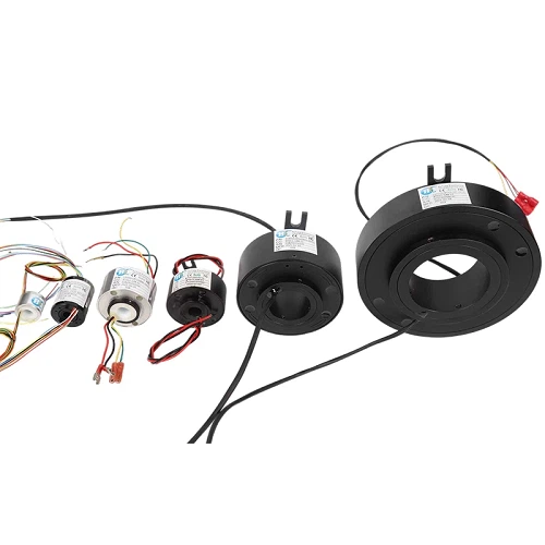
In many industrial devices, through-hole slip rings are essential components that ensure the smooth transmission of power and signals in rotating parts. Choosing the right size not only affects installation but also directly impacts the stability and lifespan of the equipment. This article will guide you on how to select the appropriate size of a through-hole slip ring.
Understanding Through-Hole Slip Ring Sizes and Their Impact on Performance
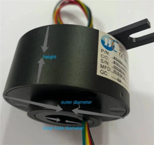
The main dimensions of a hollow shaft slip ring include inner diameter (through-hole diameter), outer diameter, and height (axial length). The inner diameter determines whether the shaft can pass through the slip ring smoothly, the outer diameter affects installation space and heat dissipation, and the height influences the number of internal conductive rings and circuit capacity. Choosing the wrong size can directly affect slip ring performance and may lead to:
• Poor installation fit: The through-hole does not match the shaft, causing installation difficulties or unstable rotation.
• Reduced electrical efficiency: If the internal space cannot accommodate the required ring structure, the number of conductive rings and circuits is limited, affecting current capacity and signal transmission.
• Thermal management issues: In compact housing, undersized conductors can overheat, reducing the reliability and lifespan of the slip ring.
Standard & Custom Size Options at ByTune
At ByTune, we offer both off-the-shelf models and fully customized slip rings. Our popular models includes:
|
Series |
Bore Size |
Outer Diameter |
Max Circuits |
Applications |
|
|
|
3mm |
18mm |
8 |
super sensors, micro robots, etc. |
|
|
|
10mm |
24mm |
24 |
medical devices, smart hardware, etc. |
|
|
|
38.1mm |
99mm |
72 |
surveillance cameras, armored vehicles, etc. |
|
|
|
150mm |
250mm |
120 |
excavators, cranes, mining machinery, etc. |
|
|
|
Custom Units |
3mm~500mm |
Flexible |
Up to 300 |
customizable, various special industrial applications |

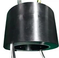

Practical Tips for Selecting the Right Size of Through-Hole Slip Ring
When choosing the size of a through-hole slip ring, consider the following practical tips:
1. Accurately Measure the Shaft Diameter
The through-hole diameter must precisely match the shaft. It is recommended to use a vernier caliper or laser measuring tool for accurate measurement.
2. Assess Equipment Space
Ensure that the slip ring's outer diameter and axial length fit within the available installation space, allowing for smooth installation without interfering with other components.
3. Consider Circuit and Channel Requirements
Choose an appropriate axial length and inner diameter based on the current and signal types to be transmitted. This ensures that conductive rings and channels can be safely accommodated.
4. Allow for Future Expansion
If possible, reserve some extra space for future circuit additions or equipment upgrades, avoiding the need to replace the slip ring later.
5. Consult Professional Manufacturers
Working with experienced suppliers, such as ByTune, can provide expert advice and customized solutions, ensuring the slip ring size perfectly matches your equipment.
FAQ
Q: How do the number and size of conductive rings affect slip ring selection?
A: Axial length and through-hole size must match the number of rings. Too few may not meet electrical needs; too many can increase size or complicate installation.
Q: What is the difference between standard and custom slip rings?
A: Standard slip rings suit common shaft sizes and channel needs. Custom slip rings are tailored for specific shaft diameters, current, channel count, or space constraints.
Q: How should I choose the slip ring size for high-speed or harsh environments?
A: For high-speed, high-vibration, or high-temperature conditions, a slightly larger outer diameter or thicker conductors can reduce wear and overheating.
Conclusion
By carefully considering the shaft diameter, available installation space, and circuit requirements, and by choosing between standard or custom solutions, you can select the most suitable slip ring size for your equipment, ensuring long-term, reliable operation.
ByTune: Your Through-Hole Slip Ring Expert
ByTune offers a wide range of through-hole slip rings in various sizes and also provides custom solutions to meet diverse application needs. Not sure which slip ring size is right for your equipment? Contact us today-our professional team will guide you and help you choose the most suitable slip ring for your device!